Table of Contents
Advertisement
AX78
Motherboard
AMD Socket AM2+/AM2
User's Manual
About this Manual:
This user's manual contains all the information you may
need for setting up this motherboard. To read the user's
manual of PDF format (readable by
the "Driver & Utility CD" into the CD-ROM drive in your
system. The auto-run screen will appear, click the
"Manual" tab to enter its submenu. If not, browse the
root directory of the CD-ROM via the File Manager, and
double click the "AUTORUN" file.
Adobe
Reader), place
AMD 770 / SB600
5200MT/s HT3.0
Dual Channel DDR2 1066
PCI Express 2.0
Gigabit LAN
SATA 3Gb/s RAID
USB 2.0
7.1-Channel HD Audio
S/PDIF Out
abit SoftMenu™ Technology
abit Silent OTES™ Technology
External CMOS Clearing
Switch
Vista Premium HW Ready
Advertisement
Table of Contents

Subscribe to Our Youtube Channel
Related Manuals for Abit AX78


Summary of Contents for Abit AX78
- Page 1 7.1-Channel HD Audio S/PDIF Out abit SoftMenu™ Technology About this Manual: abit Silent OTES™ Technology This user’s manual contains all the information you may need for setting up this motherboard. To read the user’s External CMOS Clearing manual of PDF format (readable by...
- Page 2 ○ ○ 焊接金属 ○ ○ ○ ○ ○ ○ 线材 × ○ ○ ○ ○ ○ 光盘 ○ ○ ○ ○ ○ ○ 助焊剂、散热膏、标签及 ○ ○ ○ ○ ○ ○ 其他耗材 ○: 表示该有毒有害物质在该部件所有均质材料中的含量均在 SJ/T11363-2006 标准规定的限量要求以下。 ×: 表示该有毒有害物质至少在该部件的某一均质材料中的含量超出 SJ/T11363-2006 标准规定的限量要求。 AX78...
-
Page 3: Table Of Contents
2.9 Load Fail-Safe Defaults............... 2-16 2.10 Load Optimized Defaults ............2-16 2.11 Set Password ................2-16 2.12 Save & Exit Setup..............2-16 2.13 Exit Without Saving ..............2-16 3. Driver & Utility ..............3-1 3.1 CD-ROM AUTORUN ..............3-1 AX78... - Page 4 3.6 Cool’n’Quiet Driver ............... 3-4 3.7 USB 2.0 Driver ................3-5 3.8 Acrobat Reader 8.0 ..............3-5 3.9 abit EQ (The Hardware Doctor Utility) ........... 3-6 3.10 FlashMenu (BIOS Update Utility) ..........3-7 3.11 SATA RAID Driver (for Windows Vista) ........3-8 3.12 SATA RAID Driver (for Windows XP, 2003, or 2000) .....
-
Page 5: Hardware Setup
• Onboard Gigabit LAN ™ • abit Softmenu Technology Audio ™ • abit Silent OTES Technology • Onboard 7.1-Channel HD Audio CODEC • External CMOS Clearing Switch • Supports Auto Jack Sensing and S/PDIF RoHS • 100% Lead-free process and RoHS... -
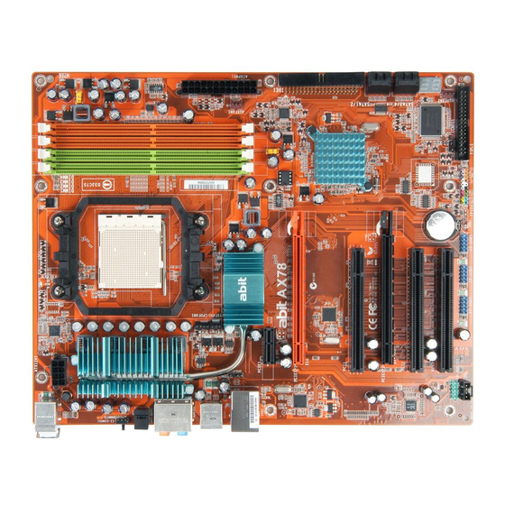
Page 6: Motherboard Layout
1.2 Motherboard Layout AX78... -
Page 7: Choosing A Computer Chassis
Install the motherboard with screws and have them tightened. To prevent shorting the PCB circuit, ※ please REMOVE the metal studs or spacers if they are already fastened on the chassis base and are without mounting-holes on the motherboard to align with. AX78... -
Page 8: Checking Jumper Settings
Set the CPU operating speed back to its default or an appropriate value. Save and exit the BIOS setup menu. Another easy way to clear the CMOS memory can be done by setting the ※ “EZ-CCMOS1” switch, see the section of “Connecting Rear Panel I/O Devices” in this manual for detail. AX78... - Page 9 Enter the BIOS setup menu. Reconfigure the setup parameters if necessary. CAUTION: Danger of explosion may arise if the battery is incorrectly renewed. ※ Renew only with the same or equivalent type recommended by the battery ※ manufacturer. Dispose of used batteries according to the battery manufacturer’s instructions. ※ AX78...
-
Page 10: Connecting Chassis Components
You may connect either a 4-pin ATX12V or an 8-pin EPS12V power source. However, it is recommended to connect the 8-pin EPS12V power source to meet the 240VA Plugged from a 4-pin Plugged from an 8-pin protection limits. ATX12V power. EPS12V power. AX78... -
Page 11: Front Panel Switches & Indicators Headers
Connects to the Suspend LED cable (if there is one) of chassis front panel. • PWR (Pin 6, 8): Connects to the Power Switch cable of chassis front panel. • PLED (Pin 16, 18, 20): Connects to the Power LED cable of chassis front panel. AX78... -
Page 12: Fan Power Connectors
CPU cooling fan connected to the “CPUFAN1” connector ※ is still capable of having its fan speed controlled. Please refer to the BIOS setup route: “PC Health Status” “CPU FANEQ Control” “CPU FAN Type” to select the one of your own. AX78... -
Page 13: Installing Hardware
CPU. The lever clicks when it’s locked into position. 3. The heatsink for CPU may have thermal interface material attached bottom. If not, applying a few squeeze of thermal paste to the CPU die will help to increase the contact. AX78... - Page 14 ※ A higher fan speed will be helpful for better airflow and heat-dissipation. Nevertheless, stay alert to not touch any heatsink since a high temperature generated by the working system is still possible. 1-10 AX78...
-
Page 15: Memory Slots
DIMM module. Static electricity can damage the electronic components of the computer or ※ optional boards. Before starting these procedures, ensure that you are discharged of static electricity by touching a grounded metal object briefly. AX78 1-11... -
Page 16: Pci Express X16 Add-On Slots (Install Graphics Card)
(For a fully configured system with two PCI Express X16 cards installed, a power supply with minimum 500W or more power output is recommended.) Refer to the instruction guide that came with the graphics card on how to run ※ its dual display mode. 1-12 AX78... -
Page 17: Connecting Peripheral Devices
Make sure to configure the “Master” and “Slave” relation before connecting ※ two drives by one single ribbon cable. The red line on the ribbon cable must be aligned with pin-1 on both the IDE port and the hard-drive connector. AX78 1-13... -
Page 18: Serial Ata Connectors
Attach either end of the signal cable to the SATA connector on motherboard. Attach the other end to the SATA device. Attach the SATA power cable to the SATA device and connect the other end from the power supply. 1-14 AX78... -
Page 19: Additional Usb 2.0 Port Headers
Data0 - Data1 - Data0 + Data1 + Ground Ground Make sure the connecting cable bears the same pin assignment. ※ 1.8.4 Internal Audio Connector This connector connects to the audio output of internal CD-ROM drive or add-on card. AX78 1-15... -
Page 20: Front Panel Audio Connection Header
To configure AC’97 front panel audio connection, please enter the BIOS setup ※ menu and select the option [AC97] via route: “Integrated Peripherals” “FP-Audio”. 1.8.6 S/PDIF Output Connection Header This header provides the S/PDIF output connection to your add-on HDMI VGA card. Pin Assignment VCC (5V) S/PDIF Out Ground 1-16 AX78... -
Page 21: Pci And Pci Express X1 Slots
1.8.7 PCI and PCI Express X1 Slots Install PCI Express X1 card into slot “PCIE1”. Install PCI cards into slots “PCI1”, “PCI2”, and/or “PCI3”. AX78 1-17... -
Page 22: Onboard Indicators
POST item and write the next POST Code into the address 80h. If the POST fails, we can check the POST Code in address 80h to find out where the problem lies. See Appendix for AWARD POST Code definitions. 1-18 AX78... -
Page 23: Power Source Indicators
1.9.2 Power Source Indicators • 5VSB: This LED lights up when the power supply is connected with power source. • VCC: This LED lights up when the system power is on. AX78 1-19... -
Page 24: Connecting Rear Panel I/O Devices
Line-Out: Connects to the front left and front right channel. Mic-In: Connects to the plug from external microphone. • LAN1: Connects to Local Area Network. • USB1/USB2: Connects to USB devices such as scanner, digital speakers, monitor, mouse, keyboard, hub, digital camera, joystick etc. 1-20 AX78... -
Page 25: Bios Setup
: Select Item F10: Save & Exit Setup (AMD770-SB600-6A66AA1AC-10) B12 Abit Over Frequency & Voltage ... In order to increase system stability and performance, our engineering staff is ※ constantly improving the BIOS menu. The BIOS setup screens and descriptions illustrated in this manual are for your reference only, and may not completely match with what you see on your screen. -
Page 26: Softmenu Setup
This item selects the external clock frequency. Due to the specification limit of the CPU you installed, the speed you set over its standard bus speed is supported, but not guaranteed. Multiplier Factor (appears only with AM2 CPU) This item displays the multiplier factor for the CPU you installed. AX78... -
Page 27: Standard Cmos Features
Total Memory 1048576K :Move Enter:Select +/-/PU/PD:Value F10:Save ESC:Exit F1:General Help F5: Previous Values F6: Fail-Safe Defaults F7: Optimized Defaults Date (mm:dd:yy) This item sets the date you specify (usually the current date) in the format of [Month], [Date], and [Year]. AX78... - Page 28 Cylinder This item configures the numbers of cylinders. Head This item configures the numbers of read/write heads. Precomp This item displays the number of cylinders at which to change the write timing. AX78...
- Page 29 640K for systems with 640K or more memory size installed on the motherboard. Extended Memory This item displays the amount of extended memory detected during system boot-up. Total Memory This item displays the total memory available in the system. AX78...
-
Page 30: Advanced Bios Features
F5: Previous Values F6: Fail-Safe Defaults F7: Optimized Defaults Virtualization Technology This option enables or disables the additional hardware capabilities provided by Virtualization Technology. Cool ’n’ Quiet Technology This option enables or disables the AMD K8 cool and quiet function. AX78... - Page 31 Don’t forget your password. If you forget the password, you will have to open ※ the computer case and clear all information in the CMOS before you can start up the system. But by doing this, you will have to reset all previously set options. AX78...
-
Page 32: Advanced Chipset Features
PCIe Configuration Click <Enter> key to enter its submenu. You may manually set the parameters through each sub-item, or leave them at their default settings. Init Display First This item allows you to choose the primary display card. AX78... -
Page 33: Integrated Peripherals
This item selects the DMA mode for devices connected through IDE channels. SATA Controller This item enables or disables the onchip SATA controller. SATA Type This item determines the mode for OnChip SATA. [Native IDE]: The on-chip SATA served as IDE mode. [RAID]: The on-chip SATA served as RAID mode. AX78... - Page 34 This item allows you to use the boot ROM (instead of a disk drive) to boot-up the system and access the local area network directly. Back to Integrated Peripherals Setup Menu FDD Controller This option enables or disables the floppy disk controller. 2-10 AX78...
-
Page 35: Power Management Setup
[0]: This option power-on the system everyday according to the time set in the “Time (hh:mm:ss) Alarm” item. [1-31]: This option selects a date you would like the system to power-on. The system will power-on on the date set, and the time set in the “Time (hh:mm:ss) Alarm” item. AX78 2-11... - Page 36 [Delay 4 Sec.]: Pushing the power button for more than 4 seconds will power off the system. This will prevent the system from powering off in case you accidentally hit or pushed the power button. [Instant-Off]: Pressing and then releasing the power button at once will immediately power off the system. 2-12 AX78...
-
Page 37: Pnp/Pci Configurations
PCI device can conduct transactions for a longer time and thus improve the effective PCI bandwidth. For better PCI performance, you should set the item to higher values. Maximum Payload Size This item sets the maximum TLP payload size for the PCI Express devices. AX78 2-13... -
Page 38: Pc Health Status
When set to [Enabled], the system will be shut down if the fan selected for monitoring is not running. CPU FANEQ Control This item allows you to control the CPU fan speed. When set to [Enabled], the following items become selectable. 2-14 AX78... - Page 39 FanEQ Temp. Tolerance This item sets the temperature tolerance range for the item “FanEQ Target Temp.”. FanEQ Start Control This item sets the speed ratio for the 3-pin fan assembly connected at “SYSFAN1” fan power connector to start running. AX78 2-15...
-
Page 40: Load Fail-Safe Defaults
This option protects the BIOS configuration or restricts access to the computer itself. 2.12 Save & Exit Setup This option saves your selections and exits the BIOS setup menu. 2.13 Exit Without Saving This option exits the BIOS setup menu without saving any changes. 2-16 AX78... -
Page 41: Driver & Utility
• [Utility]: Click to enter the utilities installation menu. • [abit Utility]: Click to enter the installation menu of utilities exclusively developed by abit. • [Browse CD]: Click to browse the contents of this “Driver-&-Utility CD”. • [Close]: Click to exit this installation menu. -
Page 42: Q-Install
3.3 ATI South Bridge Drivers To install this program: Click on the [Drivers] tab in the installation menu screen. Click the [ATI South Bridge Drivers] item. The installation screen appears. Follow the prompts on the screen to complete installation. AX78... -
Page 43: Marvel Lan Driver
Click the [Realtek HD Audio Driver] item. The installation screen appears. Follow the prompts on the screen to complete installation. After restarting the system, right-click the Sound Manager icon located at the desktop shortcut. Click item “Sound Manager”. The Realtek HD Audio Manager appears. AX78... -
Page 44: Cool'n'quiet Driver
※ an AMD Cool ‘n’ Quiet tab will appear under “Power Options” when the Cool ‘n’ Quiet software for Windows 2000 and ME is installed. This must be set to “Automatic Mode” for Cool ‘n’ Quiet to be enabled. AX78... -
Page 45: Usb 2.0 Driver
For Adobe Reader V8.0 installation in systems running versions of Windows ※ prior to Windows XP: You should have your Internet Explorer upgraded to the version later than 6.0.2600.0 before installing Adobe Reader V8.0 from the download site: http://www.microsoft.com/downloads/details.aspx?familyid=1E1550CB-5E5D-48F5-B02B- 20B602228DE6&displaylang=en AX78... -
Page 46: Abit Eq (The Hardware Doctor Utility)
The abitEQ is a self-diagnostic system that protects PC Hardware by monitoring critical items of Power Supply Voltage, CPU & System Fans Speed, and CPU & System Temperature. To install this utility: Click on the [abit Utility] tab in the installation menu screen. Click the [abit EQ] item. The following screen appears. -
Page 47: Flashmenu (Bios Update Utility)
3.10 FlashMenu (BIOS Update Utility) The FlashMenu is a utility to flash the BIOS in a more easily and quickly way. To install this utility: Click on the [abit Utility] tab in the installation menu screen. Click the [FlashMenu] item. The following screen appears. -
Page 48: Sata Raid Driver (For Windows Vista)
Save this selection and exit BIOS setup menu by accessing the BIOS menu “Save & Exit Setup”. Restart the system. The system will now boot from CD, and enter the ABIT Boot Manager, the following options appear (0) Boot From First HDD... -
Page 49: Multilingual Quick Installation Guide
• [SLED]: Connecte au câble de la DEL de veille. l’installation de votre carte mère abit. Pour des opérations plus • [PWR]: Connecte au câble de l’interrupteur de l’alimentation avancées, vous devez vous reporter à la version complète. -
Page 50: Deutsch//Kurze Installationsanleitung
Diese “Kurze Installationsanleitung” enthält nur die Anschlüsse auf der Vorderseite: [FPIO1] grundlegenden Hardwareinformationen, die Sie zur [HLED]: Kabelanschluss für Festplattenzugriffsanzeige. • Installation Ihres abit-Motherboards benötigen. Details [RST]: Kabelanschluss für Rücksetzschalter. • finden Sie im ausführlichen Handbuch. [SPKR]: Kabelanschluss für Kabelanschluss für •... -
Page 51: Italiano//Guida All'installazione Rapida
• [PLED]: collega al cavo LED alimentazione. le informazioni di base sull’hardware necessarie all’installazione della scheda madre abit. Fare riferimento Collettore porta USB aggiuntiva: [FP-USB1], [FP-USB2] alla versione completa della guida per eseguire le Collettore porta IEEE1394 aggiuntiva: [FP-1394-1], [FP-1394-2] operazioni avanzate. -
Page 52: Español//Guía Rápida De Instalación
[PWR]: Conecte el cable del interruptor de encendido. • durante la instalación de la placa base abit. Para conocer el [PLED]: Conecte el cable del LED de encendido. • funcionamiento avanzado, es necesario consultar la Terminal de puerto USB adicional: [FP-USB1], [FP-USB2] versión completa. -
Page 53: Português//Guia De Instalação Rápida
à • [PWR]: Faz a ligação ao cabo do botão de alimentação. instalação da sua placa principal abit. Para mais • [PLED]: Faz a ligação ao cabo do LED do botão de alimentação. -
Page 54: Русский//Краткое Руководство По Установке
основная информация о техническом обеспечении, которая • [PLED]: Соединяется с кабелем индикатора питания. вам может понадобиться при установке материнской платы abit. Описание дополнительных операций вы найдете в Дополнительная насадка порта USB: [FP-USB1], [FP-USB2] полной версии руководства. Дополнительная насадка порта IEEE1394: [FP-1394-1], [FP-1394-2] Предостережения... -
Page 55: Eesti//Kiirpaigaldusjuhend
4.7 Eesti//Kiirpaigaldusjuhend Käesolev “Kiirpaigaldusjuhend” sisaldab ainult [SLED]: Ühendage peatusindikaatori (Suspend LED) • abit-emaplaadi paigaldamiseks vajalikku riistvaraalast kaabliga. põhiteavet. Edasijõudnud kasutamiseks tuleb teil ikkagi [PWR]: Ühendage toitelüliti kaabliga. • pöörduda täisversiooni poole. [PLED]: Ühendage toiteindikaatori (Power LED) kaabliga. • Täiendav USB-pordi päis: [FP-USB1], [FP-USB2] Ettevaatusabinõud riistvara paigaldamisel... -
Page 56: Latviski//Ātrās Instalēšanas Instrukcija
4.8 Latviski//Ātrās instalēšanas instrukcija Šī “Ātrās instalēšanas instrukcija” ietver tikai pamata [RST]: Pievieno atiestates slēdža kabeli. • norādes iekārtai, kas nepieciešamas, instalējot abit [SPKR]: Pievieno sistēmas skaļruņa kabeli. • mātesplati. Pilnīgākai darbībai nepieciešams iegūt [SLED]: Pievieno LED pārtraukšanas kabeli. •... -
Page 57: Lietuvių//Trumpas Instaliavimo Vadovas
[SLED]: Sujunkite su darbo pristabdymo indikatoriaus • informacija apie techninę įrangą, kurios jums gali prireikti kabeliu. instaliuojant pagrindinę plokštę abit. Papildomų operacijų [PWR]: Sujunkite su maitinimo tinklo jungiklio kabeliu. • aprašymą rasite pilnoje vadovo versijoje. [PLED]: Sujunkite su maitinimo indikatoriaus kabeliu. -
Page 58: Polski//Instrukcja Szybkiej Instalacji
[SLED]: Podłączenie kabla diody LED wstrzymania pracy. • podstawowe informacje dotyczące sprzętu, wymagane [PWR]: Podłączenie kabla przełącznika zasilania. • podczas instalacji płyty głównej abit. Przy [PLED]: Podłączenie kabla diody LED zasilania. • zaawansowanych operacjach, niezbędne będzie skorzystanie z kompletnej wersji instrukcji. -
Page 59: Magyar//Gyorstelepítési Útmutató
4.11 Magyar//Gyorstelepítési útmutató Ez a “Gyorstelepítési útmutató” csak azt az alapvető [PWR]: Csatlakoztassa a tápkapcsoló kábelhez. • hardver információt tartalmazza, amely az abit alaplap [PLED]: Csatlakoztasson a táp LED kábelhez • telepítéséhez szükséges. Az előrehaladott üzemeltetéshez, Kiegészítő USB port fejrész: [FP-USB1], [FP-USB2] továbbra is a teljes útmutatót kell használnia. -
Page 60: Türkçe//Hızlı Kurulum Kılavuzu
4.12 Türkçe//Hızlı Kurulum Kılavuzu Bu “Hızlı Kurulum Kılavuzu”, abit anakartınızı takmanızda Ön Panel Konnektörleri: [FPIO1] gerekebilecek sadece temel donanım bilgisini içermektedir. [HLED]: Sabit Disk Sürücü LED kablosuna bağlayın. • İleri işlemler için daha geniş olan tam versiyonuna [RST]: Sıfırlama Anahtarı kablosuna bağlayın. - Page 61 دﻟﻴﻞ اﻟﺘﺮآﻴﺐ اﻟﺴﺮﻳﻊ اﻟﻠﻐﺔ اﻟﻌﺮﺑﻴﺔ 4.13 AX78 4-13...
- Page 62 راهﻨﻤﺎﯼ ﻧﺼﺐ ﺳﺮﻳﻊ ﻓﺎرﺳﯽ 4.14 4-14 AX78...
-
Page 63: 日本語//クイックインストールガイド
4.15 日本語//クイックインストールガイド • この「クイックインストールガイド」には、abit マ [SPKR]: システムスピーカーケーブルに接続 • [SLED]: サスペンド LED ケーブルに接続 ザーボードを取り付けるときに必要となるハードウ • [PWR]: 電源スイッチケーブルに接続 ェアの基本情報のみが含まれています。詳細な操作 • [PLED]: 電源 LED ケーブルに接続 については、その完全版を参照してください。 ハードウェアのセットアップに関する注意事項 追加 USB ポートヘッダ: [FP-USB1]、[FP-USB2] • ボードを取り付けたり設定を変更するときは、 事前に 追加 IEEE1394 ポートヘッダ: [FP-1394-1]、[FP-1394-2] 電源装置をオフにし、AC コンセントからプラグを必 ず抜いてください。 前面パネルオーディオ接続ヘッダ: [FP-AUDIO1] •... -
Page 64: 한국어//빠른 설치 가이드
4.16 한국어//빠른 설치 가이드 본 “빠른 설치 가이드”는 빅빔 abit 메인보드 • [SPKR]: 시스템 스피커 케이블에 연결하세요. • [SLED]: 유휴(Suspend) LED 케이블에 연결하세요. 설치에 필요한 중요한 하드웨어 정보만을 • [PWR]: 전원 스위치 케이블에 연결하세요. 포함하고 있습니다. 보다 상세한 정보 및 과정은... -
Page 65: Bahasa Malaysia//Panduan Pemasangan Ringkas
• maklumat perkakasan asas yang anda mungkin perlu [SPKR]: Sambungkan ke kabel Sistem Pembesar Suara. • semasa memasang papan induk abit anda. Untuk [SLED]: Sambungkan ke kabel Gantung LED. • pengendalian lanjutan, anda perlu rujuk ke versi [PWR]: Sambungkan ke kabel Suis Kuasa. -
Page 66: ไทย//คู ่ ม ื อ การติ ด ตั ้ ง อย่ า งย่ อ
เป็ น เพี ย งข้ อ มู ล พื ้ น ฐานที ่ จ ำเป็ น ใน [SPKR]:ต่ อ เข้ า กั บ สายลำโพงของระบบ • การติ ด ตั ้ ง แผงวงจรหลั ก abit ของคุ ณ เท่ า นั ้ น กรุ ณ า [SLED]:ต่ อ เข้ า กั บ สาย LED •... -
Page 67: 繁體中文
• 內建 Gigabit 網路 abit Engineered 音效 ™ • abit SoftMenu 技術 • 支援 7.1 聲道 HD 音效 • abit Silent OTES ™ 技術 • 支援自動插孔偵測以及 S/PDIF 音源輸出 • 外部 CMOS 清除開關 Serial ATA RoHS • 4 組 SATA 3Gb/s 支援 SATA RAID 0、1、... -
Page 68: 快速安裝略說
4.19.2 快速安裝略說 本「快速安裝略說」僅包含安裝 abit 主機板時所需的 附加的 USB 連接埠接頭:[FP-USB1]、[FP-USB2] 基本硬體資訊。詳細的操作方式,仍請參閱其完整的 除了位於 I/O 面板上的內建 USB 接頭外 , 您可透過帶有 手冊版本。 支架的延長線,連接這些各有兩個附加 USB 連接埠的 接頭。 硬體安裝注意事項 附加的 IEEE1394 連接埠接頭:[FP-1394-1]、[FP-1394-2] • 安裝機板或變換任何設定之前,請先關閉電源並拔 除了位於 I/O 面板上的內建 IEEE1394 接頭外,您可透 掉電源插頭。 過 帶 有 支 架 的 延 長 線 , 連 接 這 些 各 有 一 個 附 加... -
Page 69: 简体中文
• 主板内建 Gigabit 网络 abit Engineered 音效 ™ • abit SoftMenu 技术 • 支持 7.1 声道 HD 音效 • abit Silent OTES ™ 技术 • 支持自动插孔侦测以及 S/PDIF 音源输出 • 外部 CMOS 清除开关 串行 ATA RoHS • 4 组 SATA 3Gb/s, 支持 SATA RAID 0、 1、... -
Page 70: 快速安装略说
4.20.2 快速安装略说 [PLED]:连接电源 LED 电缆。 本“快速安装略说”仅包含基本的硬件信息,供您在 • 安装 abit 主板时进行参考。如需了解高级操作,仍请 附加的 USB 端口接头:[FP-USB1]、[FP-USB2] 参阅其完整的手册版本。 除了位于 I/O 面板上的板载 USB 连接器外 , 这些接头可 以通过带线卡的延长电缆分别提供两个附加的 USB 端 硬件设置注意事项 口连接。 • 在安装主板或更改任何设置前,务必关闭电源并从 附加的 IEEE1394 端口接头:[FP-1394-1]、[FP-1394-2] 交流插座上拔掉电源线。 除了位于 I/O 面板上的板载 IEEE1394 连接器外,这些 • 从防静电袋中取出主板前,应戴上静电安全腕带以 接头可以通过带线卡的延长电缆分别提供一个附加的... -
Page 71: Appendix
-Search for a valid VGA device & VGA BIOS, and put it into C000:0 1. If Early_Init_Onboard_Generator is not defined Onboard clock generator initialization. Disable respective clock resource to empty PCI & DIMM slots. 2. Init onboard PWM 3. Init onboard H/W monitor devices AX78... - Page 72 2. Set up floppy related fields in 40:hardware Detect & install all IDE devices: HDD, LS120, ZIP, CDROM … (Optional Feature) Enter AWDFLASH.EXE if: -AWDFLASH is found in floppy drive -ALT+F2 is pressed Detect serial ports & parallel ports. AX78...
- Page 73 Update keyboard LED & typematic rate 1. Build MP table 2. Build & update ESCD 3. Set CMOS century to 20h or 19h 4. Load CMOS time into DOS timer tick 5. Build MSIRQ routing table Boot attempt (INT 19h) AX78...
- Page 74 AX78...
-
Page 75: Troubleshooting (How To Get Technical Support?)
If the situation remains the same, try Step 3. Step 3. The same procedure as Step 2, but while discharging the CMOS data, pull out the ATX power connectors from motherboard and remove the button battery during CMOS discharge. AX78... - Page 76 Example: Intel 650 3.4GHz (OC FSB=220MHz) • Memory brand: Type in the brand and model name of your memory module. Example: Memory brand: Kingston (KVR533D2N4/1G) • Memory size: Type in the size of your memory module. Example: 512M* 4PCS AX78...
- Page 77 See the next page for a blank Technical Support Form, or visit our website to fill in the form on line (http://www.abit.com.tw/page/en/contact/technical.php). Q. Is the motherboard dead? Do I need to return it to where I bought from or go...
-
Page 78: Technical Support Form
5.2.2 Technical Support Form Region: E-mail: First name: Last Name: Subject: Motherboard: BIOS Version: CPU: Memory brand: Memory size: Memory configuration: Graphics card: Graphics driver version: Power supply maker: Power supply wattage: Storage devices: Optical devices: Other devices: Operating system: Problem description: AX78... -
Page 79: Contact Information
North America, South America Website: http://www.abit-austria.at Universal ABIT (USA) Corporation 3068 Laurelview Court, Shanghai Fremont, CA 94538, U.S.A. Tel: 1-510-623-0500 Universal ABIT (Shanghai) Co. Ltd. Fax: 1-510-623-1092 Room 1301, Antai Building, Website: http://www.uabit.com No. 107, Zunyi Road, Shanghai 200051 USA: sales@uabit.com... - Page 80 AX78 P/N: 4310-0001-05 Rev. 1.00...
Need help?
Do you have a question about the AX78 and is the answer not in the manual?
Questions and answers