Table of Contents
Advertisement
Advertisement
Table of Contents

Subscribe to Our Youtube Channel
Related Manuals for Kohler Lombardini LDW FOCS 502 Euro 2


Summary of Contents for Kohler Lombardini LDW FOCS 502 Euro 2
- Page 1 LDW FOCS 502 - Automotive SERVICE MANUAL...
-
Page 2: Purpose Of The Manual
Lombardini Srl Original instructions translated from the Italian language Data reported in this issue can be modified at any time by Kohler Engines . Service Manual LDW FOCS 502 automotive _ cod. ED0053027270 - 3° ed_rev. 02... -
Page 3: Preface
- For any spare parts order please specify following details: ENGINE TYPE AND SERIAL NUMBER - Version (K) - on the engine name plate - The complete and updated list of authorized Kohler service centers can be found on our web site: www.kohlerengines.com &... -
Page 4: Table Of Contents
GENERAL REMARKS AND SAFETY 5.5.1 Disassembling the rocker arm cover ....... 35 5.5.2 Disassembling the rocker arms ....... 35 - PURPOSE OF THE MANUAL ........2 5.5.3 Disassembling the fuel pump ........35 - PREFACE ..............3 5.5.4 Disassembling the injection-pumps ......36 - GENERAL SERVICE MANUAL NOTES .... - Page 5 PRE-ASSEMBLY OF CONNECTING RODS – PISTONS ......66 INSTALLING VALVES ..........66 7.4.1 Assembling the valves ..........66 INSTALLATION OF CRANK GEAR AND CRANKCASE … ..........67 7.5.1 Installing piston/connecting rod - engine block ..67 7.5.2 Assembling the crankshaft ........68 7.5.3 Assembling the crankcase ........
-
Page 6: General Safety Regulations
GENERAL REMARKS AND SAFETY INFORMATION Safety regulation GENERAL NOTES • Lombardini engines are built to provide safe and longlasting from the machine to prevent any danger resulting from its performances, but in order to obtain these results it is operation. essential that the maintenance requirements described in •... -
Page 7: Regulations For Lifting The Engine
GENERAL REMARKS AND SAFETY INFORMATION liquid must be carried out with the engine turned off and cold. Take particular care if liquids containing nitrites are mixed with others not containing these compounds as this may give rise to the formation of nitrosamines which are a health hazard. -
Page 8: General Safety During Operating Phases
GENERAL REMARKS AND SAFETY INFORMATION GENERAL SAFETY DURING OPERATING PHASES - The procedures contained in this manual have been tested and selected by the manufacturer’s technical experts, and hence are to be recognised as authorised operating methods. - A number of procedures must be carried out with the aid of equipment and tools that simplify and improve the timing of operations. -
Page 9: Information And Safety Signals
GENERAL REMARKS AND SAFETY INFORMATION Information and safety signals Accidental Starts! Explosive Fuel! DANGER DANGER Accidental Starts can cause Fuel can cause fires and severe severe injury or death. burns. Disable engine by disconnecting Do not fill the fuel tank while the negative (-) battery cable. -
Page 10: Explanation Of The Safety Pictograms
GENERAL REMARKS AND SAFETY INFORMATION Explanation of the safety pictograms that can be found on the engine or in the Workshop manual - Read the Operation and Workshop manual before - Use protective gloves before carrying out the operation performing any operation on the engine - Use protective glasses before carrying out the operation - High temperature components... -
Page 11: Technical Information
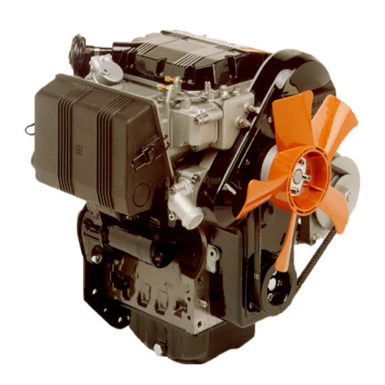
TECHNICAL INFORMATION 2.1 GENERAL DESCRIPTION OF THE ENGINE Main components A) Cylinder head L) Alternator B) Engine block M) Oil filter C) Crankcase N) Exhaust manifold D) Timing belt assembly P) Starter motor E) Flywheel and crankshaft assembly Q) Camshaft F) Air intake assembly R) Coolant pump G) Cooling fan... -
Page 12: Technical Specifications
TECHNICAL INFORMATION 2.2 TECHNICAL SPECIFICATIONS DIMENSIONS (mm) 51 ( 52 ( (1) with suction fan (2) with blower fan GENERAL DETAILS 502 Euro 2 502 Euro 4 Operating cycle 4-stroke diesel Number of cylinders n° Bore x stroke 72x62 71,5x62 Displacements Compression rate 22,5:1... - Page 13 TECHNICAL INFORMATION CONSUMPTION AT MAXIMUM POWER Specific fuel onsumption g/kWh Specific oil consumption Kg/h 0,007 SUPPLY CIRCUIT Supply type Indirect injection Fuel type Car diesel Fuel supply Electric or membrane pump Fuel filter Screw-on or in-line “fispino” Filter paper PF905 Filtering surface 2400 Filter capacity (Electrical and / or diaphragm pumps)
- Page 14 TECHNICAL INFORMATION ................................................................................................................................................................................................................................................................................................................................................................................................................................................................................................................................................................................................................................................................................................................................................................................................................................................................................................................................................................................................................................................................................................................................................................................................................................................................................Service Manual LDW FOCS 502 automotive _ cod. ED0053027270 - 3° ed_rev. 02...
-
Page 15: Alternator Load Curve Diagrams
TECHNICAL INFORMATION 2.4 ALTERNATOR LOAD CURVE DIAGRAMS Internal load curve diagram Reading taken after heat stabilisation at 25°C and constant voltage 13,5V. * To determine engine r.p.m.s, check the gear ratio adapted to pulleys. Alternator RPM * Reading taken after heat stabilisation at 20°C and constant voltage 12,5V. -
Page 16: Lubricants
TECHNICAL INFORMATION LUBRICANT SAE Classification In the SAE classification, oils differ on the basis of their viscosity, and no other qualitative characteristic is taken SAE 10W-30** into account. The first number refers to the viscosity when the engine SAE 10W-40** is cold (symbol W = winter), while the second considers SAE 10W-60** viscosity with the engine at régime. -
Page 17: Operating Principle For Lubrication
TECHNICAL INFORMATION 2.6 OPERATING PRINCIPLE FOR LUBRIFICATION Rif. Description Pressure switch Rocker-arm pin Connecting rod big end pin Oil filter cartridge Main jurnal Oil drain plug Oil dipstick Air vent Oil refilling pump Camshaft Oil pressure regulating valve Oil pump Crankshaft Oil suction filter 2.7 OPERATING PRINCIPLE FOR COOLING... -
Page 18: Operating Principle For Fuel Injection
TECHNICAL INFORMATION 2.8 . OPERATING PRINCIPLE FOR FUEL INJECTION With mechanical supply pump Rif. Description Tank Fuel filter Supply pipe Supply pump Injection pump Injector Fuel rail Exhaust pipe Plug Solenoid valve Note: the tank is supplied complete with filter on request. -
Page 19: Wiring Diagram
TECHNICAL INFORMATION 2.9 WIRING DIAGRAM With external alternator Electric pump version Rif. Description Rif. Description 40A alternator Coolant thermostat indicator light Starter motor Engine oil preassure lamp Battery (recommended 44Ah-210A-DIN) Oil preassure gauge Preheating glow plugs Battery load indicator Coolant temperature monitoring sensor Coolant thermometer Glow plug pre-heating control box Coolant thermomenter sensor... - Page 20 TECHNICAL INFORMATION With internal alternator Electric pump version Rif. Description Rif. Description 40A alternator Coolant thermostat indicator light Starter motor Engine oil preassure lamp Battery (recommended 44Ah-210A-DIN) Oil preassure gauge Preheating glow plugs Battery load indicator Coolant temperature monitoring sensor Voltage regulator Glow plug pre-heating control box Coolant thermometer...
-
Page 21: Special Tools And Equipment For Maintenance
TECHNICAL INFORMATION 2.10 SPECIAL TOOLS AND EQUIPMENT FOR MAINTANANCE Serial number Description Serial number Description Instrument for balancing injection pump Tool for lowering injection advance control delivery valve Equipment for injection advance control and Precombustion chamber extractor injector calibration Pin wrench for ring nut on pump/injector Driving shaft clamping tool pumping element Pivot pin precombustion chamber... -
Page 22: Table Of Tightening Torques
TECHNICAL INFORMATION 2.11 TABLE FOR TIGHTENING TORQUES Table of tightening torques for standard screws (coarse thread) Resistance class (R) 10.9 12.9 Quality/ Dimensions R>800N/ R>1000N/ R>1200N/ R>400N/mm R>500N/mm R>600N/mm Diameter 1000 1200 1050 1500 1800 1088 1450 2000 2400 Tightening torques for standard screws (fine threads) Resistance class (R) 10.9 12.9... - Page 23 TECHNICAL INFORMATION Tightening torques for main components Diam. & pitch Torque POSITION ( mm ) ( Nm ) Injector pump connecting rod M 3 spec. Aluminium connecting rod Steel connecting rod Preheating glow plugs 12x1,25 Rocker-arm cover Crankcase (screws for fixing crankshaft) M 10 Crankcase (screws for fixing engine block) Screw for speed governor bearing support cover...
-
Page 24: Table Of Sealants
TECHNICAL INFORMATION 2.12 TABLE OF SEALANTS Area of application Sealant Fuel rail attachment Loctite 638 Oil filter cartridge union (M 20X1,5) Loctite 601 Camshaft bearing screw (M 6) Loctite 270 Stud bolt for tightening pulley (M 10) Loctite 601 Cylinder head plug (ø 18) Loctite 510 Engine and engine block cylinder head plug (ø... -
Page 25: Malfunctions
MALFUNCTIONS 3.1 LOOKING FOR MALFUNCTIONS PROBLEM PROBABLE CAUSE Clogged pipes Clogged fuel filter Air in the fuel circuit Clogged tank breather Faulty fuel pump Blocked injector Blocked injection pump valve Injector not adjusted Excess leaking in the plunger Jammed injection pump delivery control Wrong injection pump delivery setting High oil level Blocked pressure relief valve... - Page 26 ................................................................................................................................................................................................................................................................................................................................................................................................................................................................................................................................................................................................................................................................................................................................................................................................................................................................................................................................................................................................................................................................................................................................................................................................................................................................................Service Manual LDW FOCS 502 automotive _ cod. ED0053027270 - 3° ed_rev. 02...
-
Page 27: Storing The Engine
STORING THE ENGINE 4.1 HANDLING AND LIFTING - Secure the engine using a lifting device (lifting beam) of suitable capacity. - Hook the lifting device to the points indicated in the drawing. - Before lifting, check the load’s centre of gravity. Important •... -
Page 28: Protective Treatment
STORING THE ENGINE 4.4 PROTECTIVE TREATMENT 13. Spray SAE 10W oil on the exhaust and intake manifolds. 1. Check that the engine oil and coolant are up to level. 14. Close all openings to prevent foreign bodies from entering. 2. Start the engine and keep idle at minimum speed for 15 minutes. -
Page 29: Preparing The Engine For Operation (Installed)
STORING THE ENGINE 4.6 PREPARING THE ENGINE FOR OPERATION (INSTALLED) After a period of inactivity and before installing and running the engine, it is necessary to carry out a few measures in Important order to ensure that it runs at maximum efficiency. •... - Page 30 ................................................................................................................................................................................................................................................................................................................................................................................................................................................................................................................................................................................................................................................................................................................................................................................................................................................................................................................................................................................................................................................................................................................................................................................................................................................................................Service Manual LDW FOCS 502 automotive _ cod. ED0053027270 - 3° ed_rev. 02...
-
Page 31: Removing The Assemblies
REMOVING THE ASSEMBLIES 5.1 RACCOMENDATIONS FOR REMOVING THE ASSEMBLIES - Information is given in a logical order in terms of timing and sequence of operations. The methods have been Important selected, tested and approved by the manufacturer’s • To locate specific topics, the reader should refer to the technical experts. -
Page 32: Disassembling The Exhaust Manifold
REMOVING THE ASSEMBLIES 5.2.2 Disassembling the exhaust manifold 1. Remove the dipstick tube (H). 2. Remove the exhaust manifold (L). 3. Remove the gaskets (M). 4. Close the openings and ducts to prevent foreign bodies from entering. 5.3 REMOVING THE COOLING FAN BELT DRIVE 1. -
Page 33: Disassembling The Cooling Fan Belt
REMOVING THE ASSEMBLIES 5.3.1 Disassembling the cooling fan belt (with external alternator) 1. Loosen the nuts (B - B1). 2. Loosen the belt (D) by adjusting the alternator (C) manually. 3. Remove the belt (D). 4. Remove the hub (E) and flange. pulley flange 5. -
Page 34: Disassembling The Timing Belt
REMOVING THE ASSEMBLIES 4. Loosen the screws and remove the pulley (H). 5. Remove the casing (L). 5.4.2 Disassembling the timing belt 1. Twist the pulley nut (M) to fully loosen the belt (N). 2. Remove the belt (N), working it away in sequence first from the pulley and (P) and then from the others. -
Page 35: Removing The Cylinder Head
REMOVING THE ASSEMBLIES 5.5 REMOVING THE CYLINDER HEAD 5.5.1 Disassebling the rocker arm cover 1. Remove the negative-pressure vent valve (A). 2. Remove the rocker arm cover (B). 3. Remove the gasket (C). 5.5.2 Disassebling the rocker arms 1. Press the rocker arm to fully push the drive rod down (E). -
Page 36: Disassembling The Injection-Pumps
REMOVING THE ASSEMBLIES 5.5.4 Disassembling the injection-pumps 1. Remove the fuel rail (F). Important • Make sura that the injector gaskets remain in position. 2. Unhook the spring (L). Important • If injector pumps are to be used during installation, do not loosen the screws (L1) in order to not balance injector pump deliveries during tuning. -
Page 37: Disassembling The Speed Governor And Flow Limiter
REMOVING THE ASSEMBLIES 4. Screw the extractor “7107-1460-030” onto the precombustion chamber (S) and remove it. extractor 7107-1460-027 5.5.6 Disassembling the speed governor and flow limiter 1. Remover the cover (T). 2. Extract the weights assembly (U) from the camshaft. 3. -
Page 38: Disassembling The Camshaft
REMOVING THE ASSEMBLIES 5.5.7 Disassembling the camshaft 1. Remove the cover (X). 2. Extract the camshaft (Y) from the cylinder head. Important • Make sure the drive rod has been removed and rotate the camshaft gently to remove it easily. 5.5.8 Disassembling the cylinder head 1. -
Page 39: Disassembling The Oil Pump
REMOVING THE ASSEMBLIES 4. Remove the support (C). 5.6.2 Disassembling the oil pump 1. Remove the flange (D). 2. Extract the key (E) from the crankshaft. 3. Bring piston number one (flywheel side) to the top dead centre, with the oil pump activation key in line with break in the flange, in order to be able to remove it. -
Page 40: Disassembling The Crankcase And Crankshaft
REMOVING THE ASSEMBLIES 5.6.3 Disassembling the crankcase and crankshaft 1. Remove the flange (H). 2. Tske off the gasket (L). 3. Remove the crankcase (M). 4. Remove the connecting rod cap (N). Warning • Before removing the cap, mark the area of contact with the connecting rod, in order to recognise the right position during reassembly. -
Page 41: Disassembling The Connecting Rod And Piston
REMOVING THE ASSEMBLIES 5.6.4 Disassembling connecting rod and piston 1. Extract the connecting rod/piston assembly (Q). 2. Remove the crankshaft half bearings. Warning • Before removing the crankshaft half bearings, mark the seat position, in order to recognise and match it up during reassembly. -
Page 42: Disassembling The Piston
REMOVING THE ASSEMBLIES 5.8 DISASSEMBLING THE PISTON 1. Remove the stop ring (B). 2. Extract the wrist pin (C) to separate the piston (D) from the connecting rod (E). Important • Keep each connecting rod together with its piston and wrist pin. 3. -
Page 43: Overhauls And Tuning
OVERHAULS AND TUNING 6.1 RECOMMENDATIONS FOR OVERHAULS AND TUNING - Wash the components with special detergent and do not - Information is given in a logical order in terms of timing use steam or hot water. and sequence of operations. The methods have been - Do not use flammable products (petrol, diesel, etc.) to selected, tested and approved by the manufacturer’s degrease or wash components. -
Page 44: Dimensional Check And Overhaul Of Cylinders
OVERHAULS AND TUNING 6.2.2 Dimensional check and overhaul of cylinders 1. Place the engine block on the workbench. 2. Using a micrometer, measure the diameter at points 1-2-3 (see diagram). 3. Rotate the micrometer 90° and remeasure. If ovalization or wear is greater than 0.05mm, the cylinder must be ground . -
Page 45: Dimensional Check Of Sealing Rings
OVERHAULS AND TUNING 6.2.4 Dimensional check of sealing rings 1. Place a sealing ring in the cylinder and measure the distance between the two tips using a thickness gauge (H). 2. Repeat sealing rings. If the distance between the tips does not correspond to the indicated values, replace the sealing ring with an original spare (see “Dimensional table of sealing rings”). -
Page 46: Dimensional Check And Overhaul Of Crankshaft
OVERHAULS AND TUNING 6.2.5 Dimensional check and overhaul of crankshaft 1. Wash the crankshaft thoroughly using suitable detergent. 2. Introduce a pipe cleaner into the lubrication ducts to remove any residual dirt. 3. Blow compressed air into the points indicated to free the ducts from oil. -
Page 47: Dimensional Check And Overhaul Of
OVERHAULS AND TUNING 6.2.6 Dimensional check and overhaul of connecting rods 1. Check that the contact surfaces are perfectly clean and intact. 2. Assemble the cap (D) onto the connecting rod big end connecting and tighten the screws to a torque of 38 Nm (40 Nm x PROGRESS). - Page 48 OVERHAULS AND TUNING 6.2.8 Check and overhaul of the fuel pump Disassemble the oil pump before checking or overhauling. See “Disassembling the oil pump” for the correct procedure. 1. Remove the plate (A). 2. Remove the O-ring (B). 3. Remove the sealing ring (C) from the flange and clean the seat.
-
Page 49: Overhauling The Decanting Device
OVERHAULS AND TUNING 6.2.9 Overhauling the decanting device In order to overhaul the decanting device, it is necessary to disassemble the starter motor. See “Replacing the starter motor” for the correct procedure. 1. Loosen the clamp and extract the pipe (A). 2. -
Page 50: Checking And Overhauling The Rocker Arm Pin
OVERHAULS AND TUNING 6.3.2 Checking and overhauling the rocker arm pin 1. In order to carry out a control of the rocker arm assembly, it is necessary to disassemble the cylinder head. 2. See “Disassembling the rocker arms” for the correct procedure. -
Page 51: Checking And Replacing The Camshaft
OVERHAULS AND TUNING 8. Insert a new pin (E) and drive it in 0÷1 mm from the flat part of the support. 9. Reassemble the rocker arm assembly in the cylinder head (see “Assembling the rocker arms”). 6.3.3 Checking and replacing the camshaft In order to carry out a control of the camshaft, it is necessary to disassemble it from the cylinder head. -
Page 52: Checking And Replacing The Fuel Pump Drive Rod
OVERHAULS AND TUNING 2. Use a micrometer to measure the maximum dimensions of the involutes of the intake, exhaust and injection cams (see “Table of cam dimensions”). Table of cam dimensions Dimensions (mm) Réf. 29,598÷29,650 28,948÷29,000 If the dimensions of cam involutes are lower than the values shown by 0.1mm (maximum dimension), replace the camshaft with an original spare. -
Page 53: Checking And Overhauling The Valves
OVERHAULS AND TUNING 6.3.5 Checking and overhaulimg the valves In order to carry out a control of the valves, it is valve guide necessary to remove them from the cylinder head. See “Disassembling the valves” for the correct procedure. 1. Use a gauge to measure the length of the springs (see “Table of dimensions for springs –... -
Page 54: Adjusting Valve-Rocker Arm Clearance
OVERHAULS AND TUNING 6.3.6 Adjusting valve-rocker arm clearance In order to make the adjustment, it is necessary to remove the rocker arm cover. See “Disassembling the rocker arm cover” for the correct procedure. Important • Adjustment of valve clearance must be done when the engine is cold. -
Page 55: Calibrating The Injector
OVERHAULS AND TUNING 6.3.8 Calibrating the injector Pump To carry out setting, the injector pump must be disassembled from the engine. Per conoscere la procedura corretta, vedi “Smontaggio Union pompe-iniettori”. 1. Remove the non-return valve (A) and replace it with the plug supplied with the “7107-1460-074”... -
Page 56: Checking Timing Belt Rating
OVERHAULS AND TUNING 6.4 CHECKING TIMING BELT RATING 6.4.1 Valve adjustments Fan drive pulley 1. Bring the piston to the compression top dead centre. 2. Adjust the screw (A) and the lock nut in order to adjust the rocker arm valve clearance to 2 mm. 3. -
Page 57: Diagram Of Timing Belt Rates
OVERHAULS AND TUNING 6.5 DIAGRAM OF TIMING BELT RATES Rotate the crankshaft clockwise to find out the timing rates of the entire cycle in each cylinder (operation and control). Timing belt operating angles (valve clearance 0.25 α = 14° before S (top dead center) β... - Page 58 OVERHAULS AND TUNING 4. Assemble the dial indicator on stud bolt (C). 5. Place the dial indicator tracer on the exhaust valve collar. 6. Remove the O-ring (D) from the little non-return valve and replace it with the suitable rubber cap (E) (part of tool “7107-1460-048”).
- Page 59 OVERHAULS AND TUNING 16. Rotate the crankshaft anticlockwise until liquid leaks from the pipe (M), and then stop turning when the flow is constant and without air bubbles. 17. Then turn slowly the crankshaft clockwise in order to identify the exact point at which liquid stops leaking. In these conditions, the point which coincides with the static injection timing can be identified.
-
Page 60: Balancing Injection-Pump Delivery
OVERHAULS AND TUNING 23. Once adjustment is finished, assemble the new O-rings (D) on the injector pumps. Important • The O-rings must always be replaced with original spare parts whenever the fuel rail is disassembled. 24. Apply some silicone sealant on the fuel rail seat. 25. - Page 61 OVERHAULS AND TUNING 3. Position the assembly “7107-1460-127” above the height of the injectors. assembly 4. Connect the outlet and intake pipes of the assembly 7107-1460-127 to the test heads. fuel filter Important • Be careful not to reverse the intake and outlet pipes when connecting.
-
Page 62: Adjusting Minimum And Maximum
OVERHAULS AND TUNING 6.8 ADJUSTING MINIMUM AND MAXIMUM IDLE SPEED RPMS - ( only for Euro 2 engines ) 1. Connect a revolution counter to the engine. 2. Run the engine and bring it to the operating temperature. 3. Turn the idle adjusting screw (A) and set the engine to the minimum speed required. -
Page 63: Adjusting Injection Delivery (With Dyno Brake)
OVERHAULS AND TUNING 6.9.2 Adjusting injection delivery (with dyno break) 1. Start the engine and bring it to the operating temperature. 2. Bring the engine to maximim rpm allowed. 3. Loosen the locknut (A). 4. Firmly tighten the screw (B) of the flow limiter. 5. - Page 64 Note : ..........................................................................................................................................................................................................................................................................................................................................................................................................................................................................................................................................................................................................................................................................................................................................................................................................................................................................................................................................................................................................................................................................................................................................................................................................................................................................................................................Service Manual LDW FOCS 502 automotive _ cod. ED0053027270 - 3° ed_rev. 02...
-
Page 65: Installation Of Assemblies
INSTALLATION OF ASSEMBLIES 7.1 RECOMMENDATIONS FOR INSTALLING THE ASSEMBLIES - Information is given in a logical order in terms of timing and sequence of operations. The methods have been Important selected, tested and approved by the manufacturer’s • To locate specific topics, the reader should refer to the technical experts. -
Page 66: Pre-Assembly Of Connecting Rods - Pistons
INSTALLATION OF ASSEMBLIES 7.3 PRE-ASSEMBLY OF CONNECTING RODS - PISTONS Important • Before pre-assembly, check that weight difference between the two connecting rod-piston- wrist pin assemblies does not exceed 10 g to prevent weight imbalances. 1. Lubrificate the wrist pin (A) and the seat of the small end of the connecting rod (B). -
Page 67: Installation Of Crank Gear And Crankcase
INSTALLATION OF ASSEMBLIES 4. Mount the collar (C), the spring (D), the cup (E) and the half collets (F). 5. Press down hard on the cup (E), using the special tool “7107-1460-047” to insert the half collets (F) into the valve stem groove. -
Page 68: Assembling The Crankshaft
INSTALLATION OF ASSEMBLIES 7.5.2 Assembling the crankshaft 1. Mount the half-bearings (C) and the standard shoulder half-rings (E) (flywheel side). Important • Follow the marks made during the removal phase. • The shoulder half-rings must be placed with the lubrication grooves facing outwards. 2. -
Page 69: Measuring Crankshaft Axial Clearance
INSTALLATION OF ASSEMBLIES 4. Tighten the screws (M) temporarily in alternating pattern. 5. Tighten the screws (L) in a crisscross pattern to a final torque of 50Nm. 6. Tighten the screws (M) in an alternating pattern to a engine block final torque of 10Nm. -
Page 70: Installing The Oil Pump
INSTALLATION OF ASSEMBLIES 4. Slip on a new gasket (P). 5. Replace the falnge (Q) and put in the screws (R). Important • Be careful not to damage the sealing rings during this operation. 6. Tighten the screws (R), in a crisscross pattern to a final torque of 12Nm. -
Page 71: Assembling The Flywheel
INSTALLATION OF ASSEMBLIES 5. Tighten the screws in a crisscross pattern, and tighten each of them to their respective final torques (see image). 6. Insert the key (D) into the crankshaft. 7. Install the alternator support (E) and tighten the screws to a torque of 2.2Nm. -
Page 72: Installation Of Cylinder Head And Components
INSTALLATION OF ASSEMBLIES 7.6 INSTALLATION OF CYLINDER HEAD AND COMPONENTS 7.6.1 Assembling the precombustion chamber Important • Check that the contact surfaces are perfectly clean and intact. 1. Install the precombustion chamber (A), so that its hole (H) coincides with the one on the pre-heating glow plug. -
Page 73: Assembling The Cylinder Head
INSTALLATION OF ASSEMBLIES 7.6.2 Assembling cylinder head Important • Make sure there are no foreign bodies or residual material in the cylinder head cavity. • Check that the contact surfaces are perfectly clean and intact. 1. Slip on a new gasket (G). 2. -
Page 74: Assembling The Speed Governor And Flow Limiter
INSTALLATION OF ASSEMBLIES 7.6.4 Assembling the speed governor and flow limiter Important • Make sure that all components are perfectly clean and dry. • Check that all components are intact and, if limiter flow necessary, replace them with original spares. 1. -
Page 75: Assembling Injection-Pumps
INSTALLATION OF ASSEMBLIES 7.6.5 Assembling injection-pumps Important • Check that all components are intact and, if necessary, replace them with original spares. • Before replacing the injectors it is always necessary to replace the flameproof bulkhead, the copper gasket and the oil and diesel O-ring seals. •... -
Page 76: Assembling The Mechanical Fuel Pump
INSTALLATION OF ASSEMBLIES 11. Tighten the screws (T) to a torque of 1,1 Nm. 12. Balance the injector deliveries (see “Balancing injector pump deliveries”). 13. Put the new O-rings on the injector pumps. fuel rail 14. Apply sealant to the seat of the fuel rail. 15. -
Page 77: Assembling The Rocker Arms
INSTALLATION OF ASSEMBLIES 7.6.7 Assembling the rocker arms Important • Check that the contact surfaces are perfectly clean and intact. 1. Press down hard on the pump stroke to insert the pin, which facilitates assembly of the drive rods (B). 2. -
Page 78: Installing The Timing Belt Drive
INSTALLATION OF ASSEMBLIES 7.7 INSTALLING THE TIMING BELT DRIVE 7.7.1 Assembling the timing belt pulley 1. Insert the key (B) into the crankshaft. 2. Mount the pulley (A). 3. Mount the pulley (C) and tighten the screw to a torque 80 Nm. -
Page 79: Assembling The Belt Drive Cover
INSTALLATION OF ASSEMBLIES 4. Insert tool “7107-1460-049” in the tensioner holder lever. 5. Calibrate the torque wrench to 20 Nm and insert it tool 7107-1460-049 into the tool, with the lever perpendicular to the belt. 6. Loosen the nut slightly (D). 7. -
Page 80: Installation Of The Cooling Fan Belt Drive
INSTALLATION OF ASSEMBLIES 7.8 INSTALLATION OF THE COOLING FAN BELT DRIVE 7.8.1 Assembling the fan belt drive pulleys 1. Check that all components are intact and, if necessary, replace them with original spares. 2. Mount the pulley (G1) and fasten the screws without tightening them. -
Page 81: Assembling The Fan Belt Drive
INSTALLATION OF ASSEMBLIES 9. Mount the pulley (P), washers and spacer. 10. Tighten the screw (Q) to a torque of 25 Nm. 7.8.2 Assembling the fan belt drive With internal alternator With external alternator The engine may have an external or internal alternator. With internal alternator 1. -
Page 82: Assembling The Cooling Fan
INSTALLATION OF ASSEMBLIES 7.8.3 Assembling the cooling fan 1. Check that the fan is intact and, if necessary, replace it with an original spare. 2. Install the cooling fan (U). 3. Tighten the screws to a torque of 10 Nm. screw 7.9 INSTALLING INTAKE AND EXHAUST MANIFOLDS 7.9.1 Assembling exhaust manifold... - Page 83 INSTALLATION OF ASSEMBLIES 7. Clean the cover (H) witha a jet of air. 8. Check the state of the filter cartridge (G). If necessary, remove the cartridge, knock it repeatedly against a flat surface to eliminate dirt and clean with a jet of air.
- Page 84 Notes : ..........................................................................................................................................................................................................................................................................................................................................................................................................................................................................................................................................................................................................................................................................................................................................................................................................................................................................................................................................................................................................................................................................................................................................................................................................................................................................................................................Service Manual LDW FOCS 502 automotive _ cod. ED0053027270 - 3° ed_rev. 02...
-
Page 85: Replacing Parts
REPLACING PARTS 8.1 RACCOMMENDATIONS FOR REPLACING PARTS - This chapter describes the procedures for replacing a number of components and/or assemblies which are Important not recommended for repairs. • To locate specific topics, the reader should refer to the index. - Some of these operations are also contained in the user’s operation and maintenance manual. - Page 86 REPLACING PARTS 5. Adjust the alternator manually while at the same time tightening the screw to regulate belt tension. Important • Use the method shown in the diagram to check belt tension. The resultant (R) must be 10÷15 mm. 6. Tighten the nuts (B -B1) to a final torque of 40 Nm and 25 Nm respectively.
-
Page 87: Replacing The Timing Belt
REPLACING PARTS 9. Install the cooling fan. 10. Tighten the screws to a torque of 10 Nm. cooling fan flange fan hub pulley 8.3 REPLACING THE TIMING BELT 5. Check the timing belt rating (see “Checking timing belt rating”). Important 6. -
Page 88: Replacing The Air Filter
REPLACING PARTS 8.5 REPLACING THE AIR FILTER Important • Polluting substances should be disposed of properly, in full compliance with the law. • Replacement may be carried out with the engine installed on the machine. Air filter (square type) 1. Switch off the engine and leave to cool. 2. -
Page 89: Replacing The Alternator
REPLACING PARTS 8.6 REPLACING THE ALTERNATOR Warning • Replacement may be carried out with the engine installed on the machine. 1. Switch off the engine and leave to cool. 2. Disconnect the battery. 3. Disconnect the electrical connectors. 4. Loosen the nut (A). 5. -
Page 90: Replacing The Flywheel Ring Gear
REPLACING PARTS 8.8 REPLACING THE FLYWHEEL RING GEAR In order to replace the ring gear, it is necessary to disassemble the flywheel. See “Disassembling the flywheel” for the correct procedure. 1. Cut the ring gear (A) in several places using a chisel and remove it. -
Page 91: Replacing The Coolant Pump
REPLACING PARTS 8.10 REPLACING THE COOLANT PUMP Important • Replacement may be carried out with the engine installed on the machine. Coolant pump 1. Switch off the engine and leave to cool. 2. Disassemble the cooling fan (see “Removing the cooling fan belt drive”). -
Page 92: Replacing The Negative-Pressure Vent Valve
REPLACING PARTS 8.12 REPLACING THE NEGATIVE-PRESSURE VENT VALVE Important • Replacement may be carried out with the engine installed on the machine. Caption 1. Switch off the engine and leave to cool. 1) Nut 2. Loosen nut (A). 2) Bushing 3. -
Page 93: Replacing Injector Pump Parts
REPLACING PARTS 8.14 REPLACING INJECTOR PUMP PARTS Exploded diagram of the injector pump The figure shows the injector pump parts. Caption 1. Tension washer 2. Tappet 3. Stop collar 4. Plunger 5. Spring 6. Screw 7. Support 8. Lever 9. Ring nut 10. - Page 94 REPLACING PARTS 9. Check the good seal of the delivery valve (12) as well as of the pumping element (parts 4-11). If necessary, replace them with original spare parts. 10. Assemble all parts (15-14-13). 11. Assemble the delivery valve (12). tool 7107-1460-029 Important •...
-
Page 95: Replacing The Nozzle-Injector
REPLACING PARTS 8.14.2 Replacing nozzle-injector Important • Replacement may be carried out with the engine installed on the machine. 1. Disassemble injection pump (see “Disassembling injection pumps”). 2. Loosen the ring-nut (21). 3. Extract the nozzle (23) and the parts (24-25-26-27). 4. - Page 96 ..........................................................................................................................................................................................................................................................................................................................................................................................................................................................................................................................................................................................................................................................................................................................................................................................................................................................................................................................................................................................................................................................................................................................................................................................................................................................................................................................Service Manual LDW FOCS 502 automotive _ cod. ED0053027270 - 3° ed_rev. 02...
- Page 97 ..........................................................................................................................................................................................................................................................................................................................................................................................................................................................................................................................................................................................................................................................................................................................................................................................................................................................................................................................................................................................................................................................................................................................................................................................................................................................................................................................Service Manual LDW FOCS 502 automotive _ cod. ED0053027270 - 3° ed_rev. 02...
Need help?
Do you have a question about the Lombardini LDW FOCS 502 Euro 2 and is the answer not in the manual?
Questions and answers