
Related Manuals for Tranberg TEF 4900


Summary of Contents for Tranberg TEF 4900
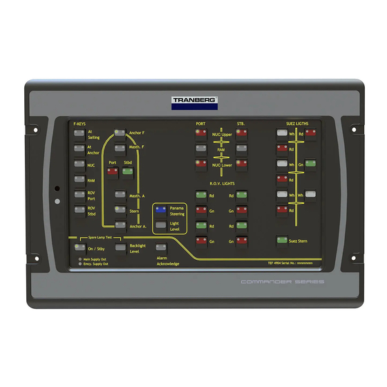
- Page 1 Installation and User Manual Tranberg 4900 Commander Control system Version 2.9 R. STAHL TRANBERG AS Feb. 2021 Copyright © 2005 – 2021 R. STAHL TRANBERG AS. All rights reserved.
- Page 2 R. STAHL TRANBERG AS R&D R. STAHL TRANBERG AS has made every effort to provide accurate information, but makes no claims as to the accuracy or completeness of this information. R. STAHL TRANBERG AS disclaims liability for errors, omissions, misinterpretation or misuse of this information by others.
-
Page 3: Table Of Contents
Relay output modules ...................... 29 Analog output modules ....................30 Connections and fuses ....................31 CHAPTER VII. INSTALLATION ..................32 7.01 I ..................32 ECTION NTRODUCTION Copyright © 2005 – 2021 R. STAHL TRANBERG AS. All rights reserved. Page iii of 38... - Page 4 CHAPTER VIII. APPROVALS ..................37 8.01 A ................... 37 ECTION PPROVALS CHAPTER IX. ADDITIONAL INFORMATION ..............38 9.01 T ..............38 ECTION ECHNICAL LARIFICATIONS Copyright © 2005 – 2021 R. STAHL TRANBERG AS. All rights reserved. Page iv of 38...
-
Page 5: Chapter I. Introduction
Each node is given a unique address and the corresponding action between a single button and the panel is defined in the configuration of the sys tem. Copyright © 2005 – 2021 R. STAHL TRANBERG AS. All rights reserved. Page 5 of 38... -
Page 6: Technical Overview
Generic system diagram: Panel 1 Panel 2 Panel 3 RS-485 Network Master Config data RS-485 Network Output module 1 Output module 2 Output module 3 Copyright © 2005 – 2021 R. STAHL TRANBERG AS. All rights reserved. Page 6 of 38... -
Page 7: Functional Description
Functional description Section 3.01 Introduction The TEF 4900 Commander remote control system can have to up to 7 operator panels connected in one system. Each operator panel consist of up to 64 buttons, each stacked up to 8 rows. The panels are backlit for easy reading of text and graphics, in daylight as well as at night. -
Page 8: Text And Graphics On Panel
This is an unacknowledged alarm. When pressed at this stage, the button will flash green and the spare output will be switched on. Copyright © 2005 – 2021 R. STAHL TRANBERG AS. All rights reserved. Page 8 of 38... - Page 9 In any case the user will have control over each single button by turning this on or off. See the two chapters Button and led status and Button state diagram over the next two pages. Copyright © 2005 – 2021 R. STAHL TRANBERG AS. All rights reserved. Page 9 of 38...
-
Page 10: Button And Led Status
Another press on the key at this state will return to state 0 and a message to turn the output off. Copyright © 2005 – 2021 R. STAHL TRANBERG AS. All rights reserved. Page 10 of 38... -
Page 11: Button Configurations
The setup of F-keys is specific for each system, please refer to project drawings for details. Copyright © 2005 – 2021 R. STAHL TRANBERG AS. All rights reserved. Page 11 of 38... -
Page 12: Spare Lamp Test
Rapid green flashing: Circuit on, unconfirmed status. Green steady: Main lamp on. Slow green flashing: Spare lamp on. Red flashing: Unacknowledged alarm. Red Steady: Acknowledged alarm. Copyright © 2005 – 2021 R. STAHL TRANBERG AS. All rights reserved. Page 12 of 38... -
Page 13: Master Cpu
Alarm Silence button will flash continuously (provided the connection towards the panel is ok). S ee also Chapter V Panels, Section 5.01 Overview, Power Supply Monitoring. Copyright © 2005 – 2021 R. STAHL TRANBERG AS. All rights reserved. Page 13 of 38... -
Page 14: Vdr Gateway
3 = Output failure, 4 = Net and output failure. If node is set to Manual override, the code is 3 or 4. Net1 – Net4: Status of the (up to) 4 independent power supply networks. 1 = On, 0=Off. Copyright © 2005 – 2021 R. STAHL TRANBERG AS. All rights reserved. Page 14 of 38... - Page 15 Total number of characters (including commas) sent are 47 characters, plus carriage return and new line. Packet lengths are shorter in case of irregularities (see later in this document). Copyright © 2005 – 2021 R. STAHL TRANBERG AS. All rights reserved. Page 15 of 38...
- Page 16 Dimmer and flasher value: Value Dimmer level Flasher rate (blink / min.) ‘0’ 0 (off) 0 (off) ‘1’ ‘2’ ‘3’ ‘4’ ‘5’ ‘6’ ‘7’ 100 (max) Copyright © 2005 – 2021 R. STAHL TRANBERG AS. All rights reserved. Page 16 of 38...
- Page 17 Errorno. Message Description $IIALR,,,V,V,*73 No alarm $IIALR,,001,A,V,Output failure*2A unacknowledged $IIALR,,001,A,A,Output failure*3D acknowledged $IIALR,,002,A,V,Power failure*49 unack. $IIALR,,002,A,A,Power failure*5E ack. $IIALR,,003,A,V,Comm. failure*15 unack. $IIALR,,003,A,A,Comm. failure*02 ack. Copyright © 2005 – 2021 R. STAHL TRANBERG AS. All rights reserved. Page 17 of 38...
-
Page 18: Scada Gateway
Checksum MSB: The MSB of the checksum (e.g. 1 if the ch ecksum is 16). Checksum LSB: The LSB of the checksum (e.g. 6 if the checksum is 16). Copyright © 2005 – 2021 R. STAHL TRANBERG AS. All rights reserved. Page 18 of 38... - Page 19 When calculating the checksums, the ASCII value of each character shall been used. Copyright © 2005 – 2021 R. STAHL TRANBERG AS. All rights reserved. Page 19 of 38...
- Page 20 Power on panel: Send ASCII character 48 “0” for OFF. Send ASCII character 49 “1” for ON Panel address Panel ASCII char ASCII code Copyright © 2005 – 2021 R. STAHL TRANBERG AS. All rights reserved. Page 20 of 38...
- Page 21 Button numbers Comments On/Off < > ‘ Backlight dim Alarm ack Note: The panel dim function cannot be remotely controlled. Copyright © 2005 – 2021 R. STAHL TRANBERG AS. All rights reserved. Page 21 of 38...
- Page 22 (output failure and communication failure). To acknowledge these alarms, the panel has to be operated. Errorno. Message Description $IIACK,000*55 General acknowledge $IIACK,001*54 (General acknowledge) $IIACK,002*57 (General acknowledge) $IIACK,003*56 (General acknowledge) Copyright © 2005 – 2021 R. STAHL TRANBERG AS. All rights reserved. Page 22 of 38...
-
Page 23: Chapter V. Panel
The communication circuitry has a built-in snubber circuit which eliminates the need of end resistor. The transceiver circuit is short circuit safe and is overvoltage protected. Copyright © 2005 – 2021 R. STAHL TRANBERG AS. All rights reserved. Page 23 of 38... -
Page 24: Buttons And Leds
(even if the power supply has recovered), and light steady when the alarm is acknowledged (if the supply net is still missing). Copyright © 2005 – 2021 R. STAHL TRANBERG AS. All rights reserved. Page 24 of 38... -
Page 25: Settings On The Panel
The CPU in the panel includes non-volatile memory. This is used to register the state of each button. Upon a complete power loss, this memory is read and the button statuses are set accordingly. Copyright © 2005 – 2021 R. STAHL TRANBERG AS. All rights reserved. Page 25 of 38... -
Page 26: Connections
The 24VDC power is connected on the rear of the panels using regular screw terminals. RS-485 network The network is connected on the rear of the panels using RJ-45 terminals. Copyright © 2005 – 2021 R. STAHL TRANBERG AS. All rights reserved. Page 26 of 38... -
Page 27: Output Modules
Never change the addresses, and if replacing a module, please ensure that the address of the new module is identical to the replaced module. Copyright © 2005 – 2021 R. STAHL TRANBERG AS. All rights reserved. Page 27 of 38... - Page 28 There are four LEDs on each output module: Power indicates that logic power supply (24VDC) is present to the module, Rx indicates messages received to the module, T x Copyright © 2005 – 2021 R. STAHL TRANBERG AS. All rights reserved. Page 28 of 38...
-
Page 29: Relay Output Modules
Ch. 1 Ch. 2 Main S. Emcy. S. Ch. 3 Ch. 4 Ch. 5 Ch. 6 Main S. Emcy. S. Ch. 7 Ch. 8 Copyright © 2005 – 2021 R. STAHL TRANBERG AS. All rights reserved. Page 29 of 38... -
Page 30: Analog Output Modules
Disconnect power to the module for a f ew seconds, and then reconnect. The module will work as before but the current supervision will be turned off. Copyright © 2005 – 2021 R. STAHL TRANBERG AS. All rights reserved. Page 30 of 38... -
Page 31: Connections And Fuses
(24VDC) is present to the module, Rx indicates messages received to the module, T x indicate messages sent out from the module, while Fault indicate a failure in the module or the main supply net is missing. Copyright © 2005 – 2021 R. STAHL TRANBERG AS. All rights reserved. Page 31 of 38... -
Page 32: Installation
Each module has been factory set with correct node addresses and labeled accordingly. Do not make any changes. Copyright © 2005 – 2021 R. STAHL TRANBERG AS. All rights reserved. Page 32 of 38... -
Page 33: Section 7.04 Main Power Supplies
Connect the various power sources (up to four) as described in the provided system data sheets. Connect 24VDC power to other modules and panel. Connect the communication cable. Copyright © 2005 – 2021 R. STAHL TRANBERG AS. All rights reserved. Page 33 of 38... -
Page 34: Section 7.06 Termination Of Outputs
Each connected module is queried by the Master CPU repeatedly, and as each module replies, a yellow led (Tx) is lit up for a fraction of a second. Copyright © 2005 – 2021 R. STAHL TRANBERG AS. All rights reserved. Page 34 of 38... -
Page 35: Section 7.08 Testing The System
If the Activity led in the Master CPU is constantly on, it indicates a failure somewhere in the network. Check the above; if the yellow led in the power Copyright © 2005 – 2021 R. STAHL TRANBERG AS. All rights reserved. Page 35 of 38... - Page 36 If the failure has been corrected, label the new module in the same way as the faulty module, e.g. M3, and set a sticker on top of the address dial sw itch to avoid anyone altering this. Copyright © 2005 – 2021 R. STAHL TRANBERG AS. All rights reserved. Page 36 of 38...
-
Page 37: Chapter Viii. Approvals
Chapter VIII. Approvals Section 8.01 Approvals Type approved by DNV-GL. Copyright © 2005 – 2021 R. STAHL TRANBERG AS. All rights reserved. Page 37 of 38... -
Page 38: Additional Information
Please contact R. STAHL TRANBERG AS regarding clarifications: Visiting and postal address Strandsvingen 6 N-4032 Stavanger NORWAY Tel: +47 51 57 89 00 Fax: +47 51 57 89 50 info.no-st@r-stahl.com www.stahl-tranberg.com Copyright © 2005 – 2021 R. STAHL TRANBERG AS. All rights reserved. Page 38 of 38...
Need help?
Do you have a question about the TEF 4900 and is the answer not in the manual?
Questions and answers