Advertisement
Quick Links
Read this guide thoroughly and follow the installation and operation proce-
dures carefully in order to prevent any damage to the units and/or any de-
vices that connect to them.
This package contains:
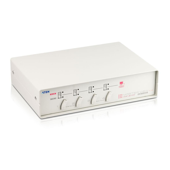
M 1 Master View CS-114A KVM Switch
M 1 Power Adapter
M 1 User Manual
If anything is damaged or missing, contact your dealer.
© Copyright 2000 ATEN International Co., Ltd.
Manual Part No. PAPE - 1151-200
Printed in Taiwan 06/2000
All brand names and trademarks are the registered property of their respective owners.
2001 - 01 -03
Advertisement

Related Manuals for ATEN Master View CS-114A


Summary of Contents for ATEN Master View CS-114A
- Page 1 This package contains: M 1 Master View CS-114A KVM Switch M 1 Power Adapter M 1 User Manual If anything is damaged or missing, contact your dealer.
- Page 2 The Master View CS-114A 4 Port KVM (Keyboard, Video, Mouse), Switch is a control unit that allows access to four computer systems from a single PS/2 keyboard, PS/2 mouse, and monitor console in a cost effective manner. There are three convenient methods to access the computers: Pushbutton Selection Switches;...
- Page 3 * See the note under Cables in the next section. Although it is possible to use standard cables to connect the PCs to the CS-114A, for optimum signal integrity and to simplify the layout, we strongly recommend that you use the following high quality CS Custom...
- Page 4 1. On Line and Selected LEDs: M When an On Line LED is lit, it indicates that the computer at- tached to the corresponding port is up and running. M When a Selected LED is lit, it indicates that the port it corre- sponds to is the currently selected port.
- Page 5 1. Power Jack The CS-114A is designed to be non-powered (external power is not required - its operation power comes from the computers). In general, the only time that external power is required is when you daisy chain it, or if operation becomes erratic because the unit isn’t obtaining enough power from the computer connections.
- Page 6 The most basic installation is a Single Stage installation, in which no additional Master View’s are daisy chained down from the first unit. The Master View CS-114A design also allows additional units to be daisy chained down to two or three levels. To set up a single stage installation do the following: 1.
- Page 7 To control even more computers, up to four additional Master View CS-114A units can be cascaded from the CPU ports of the First Stage unit. The cascaded Master Views that connect back to the First Stage unit are considered Second Stage units. As many as 16 computers can be controlled in a complete two stage installation.
- Page 8 The procedures for setting up a three stage installation are essentially the same as for a two stage installation. With a three stage setup, however, as many as 64 computers can be controlled in a complete installation. Note: Master View units cannot be cascaded beyond the third level. - 7 - 2001 - 01 -03...
-
Page 9: Manual Port Selection
Manual Port Selection Manual port selection is accomplished either with the Port Selection switches on the front panel of the Master View CS-114A unit, or with an optional foot switch. M Port Selection Switches: Press the Port Selection switch of the unit that corresponds to the computer that you want to access. -
Page 10: Hotkey Port Selection
Hotkey Port Selection Hotkey Port Selection allows you to select the active computer directly from the keyboard. The Master View CS-114A provides the following Hotkey Port Selection features: M Selecting the Active Port M Auto Scan Mode M Last/Next Mode Hotkey Port Selection is activated with one of two combinations: M The default combination is [Alt+Ctrl+Shift]. - Page 11 To access a computer attached to a Second Stage unit, key in a two digit number for the Port ID (press and release each number separately). The first digit represents the CPU Port number (1 - 4), on the First Stage unit that the Second Stage unit is cascaded down from;...
- Page 12 Last/Next Mode: Last/Next mode enables you to easily switch from the currently active computer to the previous or next available computer in the installation. There are two methods of invoking Last/Next Mode: Basic Mode, and Quick Mode.The choice of mode is made with DIP Switch 4. Set the switch to Off for Basic Mode;...
- Page 13 Activity DIP Switch Port Select [Alt+Ctrl+Shift] 3 On Port ID [Enter] [LCtrl+RCtrl] 3 Off Port ID [Enter] Auto Scan [Alt+Ctrl+Shift] 3 On [Enter] [LCtrl+RCtrl] 3 Off [Enter] Basic Last/Next Mode [Alt+Ctrl+Shift] 3 On [Enter] LShift - Last; RShift - Next [LCtrl+RCtrl] 3 Off LShift - Last;...
- Page 14 Note: The default position for all settings is ON. Scan Time - Switch 1 & 2: Seconds Switch1 Hotkey Select - Switch 3 / Last/Next Mode Select - Switch 4: See the Hotkey Summary Table on page 12. Function Power Consumption 800 mW PC Connections Direct...
- Page 15 Extender Cable with you cannot use a Serial-to-PS/2 adapter at the Mouse Port Adapters at end that plugs into the CS-114A. Use a PS/2 Both Ends extender cable with a mouse adapter on the end that plugs into the computer.
- Page 16 Video Problems Resolution and/or This unit supports VGA, SVGA, Multisync, Bandwidth set too high. and XGA (interlaced), with resolutions of up to 1920x1440. The maximum bandwidth is 180 MHz. Cable quality not good We strongly recommend that you use high enough.
Need help?
Do you have a question about the Master View CS-114A and is the answer not in the manual?
Questions and answers