Table of Contents

Subscribe to Our Youtube Channel
Related Manuals for Euromag MUT2200EL


Summary of Contents for Euromag MUT2200EL
- Page 1 ELECTROMAGNETIC FLOWMETERS Sensors Instruction manual MUT2200EL/US MUT2300 /US MUT1000EL/US MUT1100J MUT1222 MUT2660 MUT2770 CAREFULLY READ THESE INSTRUCTIONS AND KEEP THEM IN A SAFE PLACE ENGLISH Translation of the original instructions TD-217-1-ENG...
- Page 2 This document must be delivered to the user before machine installation and commissioning. Symbols used in this manual In order to draw the attention of all personnel working with the equipment supplied by EUROMAG INTERNATIONAL, the points of particular importance described in this manual are highlighted with graphic signs and different colors that will make them easily identifiable.
-
Page 3: Table Of Contents
OPERATING PRINCIPLE ......................9 2.1.1 Bidirectional reading ........................9 AVAILABLE VERSIONS ......................10 2.2.1 Flanged sensors ......................... 10 • MUT2200EL – Full Bore ......................10 • MUT2300 – Reduced Bore ....................10 2.2.2 Wafer sensors ..........................10 • MUT1000EL - Wafer ......................10 •... - Page 4 Calculation of the insertion depth ....................48 7.5.3 Installation of the sensor ......................49 7.5.3.1 Preparation of the pipe ........................ 49 7.5.3.2 Installation of the flowmeter ....................... 49 7.5.4 Flowmeter grounding ........................50 4 / 54 4 / 54 EUROMAG | SENSORS | Ed. 04/2019...
- Page 5 GROUNDING CHECK ........................ 50 CLEANING OF EBONITE COATINGS: ..................50 TROUBLESHOOTING CERTIFICATIONS AND TECHNICAL FEATURES SENDING THE FLOWMETER TO THE MANUFACTURER 11.1 REPAIR REQUEST FORM ......................51 PRODUCT DISPOSAL EUROMAG | SENSORS | Ed. 04/2019 5 / 54 5 / 54...
-
Page 6: Introduction
The manufacturer will be held responsible only if the converter will be used in its original configuration. For applications that require high working pressures or use of substances that may be dangerous for people, the environment, equipment, or anything else: In case of pipe breakage, EUROMAG INTERNATIONAL recommends taking necessary precautions, such as adequate positioning and protection or installation of a guard or safety valve, before installing the CONVERTER in the COMPACT version. -
Page 7: Preliminary Notes
3. The input and output distances must be on recommended settings 4. The grounding instructions must be followed PRODUCT IDENTIFICATION Each Sensor manufactured by EUROMAG INTERNATIONAL has an identification plate (Fig. 1) that displays the following information:: IDENTIFICATION PLATE » MODEL: Sensor model »... -
Page 8: Applications
Sensors APPLICATIONS The sensors manufactured by the company EUROMAG are widely used in many applications where it is important to measure the flow rate of electrically conductive liquids. Various models can be used in different applications. The table below shows the typical applications according to the individual sensor models manufactured by EUROMAG. -
Page 9: Product Description
Furthermore, since they do not use any moving parts, they require virtually no maintenance. EUROMAG electromagnetic flowmeters cover a wide variety of applications (e.g., water flowmeters, wastewater flow measurement, fertilizer flow measurement, etc.) and respond to every customer request thanks to the wide range of models. -
Page 10: Available Versions
Sensors AVAILABLE VERSIONS EUROMAG manufactures its sensors in different versions, each intended for use in different applications, as summarized in the paragraph “1.5 Applications.” The different sensor versions available are shown below. 2.2.1 Flanged sensors • MUT2200EL – Full Bore •... -
Page 11: Installation
Do not move the flowmeter with the lifting device if it is not in the original packaging (Fig. 4) or without adequate support that ensures the required stability. Fig. 2 Fig. 3 Fig. 4 EUROMAG | SENSORS | Ed. 04/2019 11 / 54 11 / 54... -
Page 12: General Installation Requirements
Install a suitable anti-vibration protection if vibrations occur. Fig. 7 Installation with anti-vibration protections 3.2.2 Magnetic fields • AVOID exposing the flowmeter to strong or nearby magnetic fields. Fig. 8 Avoid magnetic fields 12 / 54 12 / 54 EUROMAG | SENSORS | Ed. 04/2019... -
Page 13: Negative Pressure
Max. Coating in EBONITE +176 Coating in PTFE (remote) +130 +266 Coating in PTFE (compact) +176 Coating in PTFE (separate high temperature) +180 +356 MUT1100J +176 INSERZIONI +176 EUROMAG | SENSORS | Ed. 04/2019 13 / 54 13 / 54... -
Page 14: Installation Conditions
For partially filled pipes or with downward flow and free exit, the flowmeter should be placed in a U-shaped tube (see Fig. 13). Full bore Sensors Reduced bore Sensors 5 D N 0 D N Fig. 13 Installation on U-shaped tube 14 / 54 14 / 54 EUROMAG | SENSORS | Ed. 04/2019... - Page 15 “T” connection downstream of the flowmeter 1 0 D N Fig. 15 Installation on U-shaped tube Three-dimensional curves 1 0 D N Fig. 16 Installation near three-dimensional bends EUROMAG | SENSORS | Ed. 04/2019 15 / 54 15 / 54...
- Page 16 We recommend installing the sensor on a vertical/sloped pipe with an upward flow direction (Fig. 19) to minimize the wear and deposits in the sensor. Avoid the installation on vertical pipes with free exit (Fig. 20). Fig. 19 Correct position Fig. 20 Incorrect position 16 / 54 16 / 54 EUROMAG | SENSORS | Ed. 04/2019...
- Page 17 We recommend installing gate valves downstream of the meter. Fig. 22 Gate valves installation In order to avoid a vacuum, always install the sensor downstream of the pump and NEVER upstream. Fig. 23 Avoid negative pressure EUROMAG | SENSORS | Ed. 04/2019 17 / 54 17 / 54...
-
Page 18: Installation
Also avoid the following positions (*) : Fig. 27 Correct position Fig. 28 Incorrect position Fig. 29 Incorrect position (*) Note: Insertion meters can also be installed horizontally. 18 / 54 18 / 54 EUROMAG | SENSORS | Ed. 04/2019... -
Page 19: Sensor Support
Standard bolts must be lubricated well and tightened evenly around the gasket. If the bolts are over- tightened, leakage or damage to the flowmeter or piping may occur. EUROMAG | SENSORS | Ed. 04/2019 19 / 54 19 / 54... -
Page 20: Wafer Sensors
All the values are theoretical and have been calculated for optimal conditions and with the use of carbon steel flanges. • Wafer Sensors Flat Gasket Grounding Rings O-Rings Piping Flanges Stud Bolt Flat Washer Fig. 34 Flange tightening 20 / 54 20 / 54 EUROMAG | SENSORS | Ed. 04/2019... - Page 21 OR NBR 4xM12 4xM12 4xM16 4xM16 4xM16 4xM16 8xM16 8xM16 8xM16 8xM16 8xM20 8xM20 12xM20 12xM20 12xM24 12xM20 12xM24 16xM20 16xM24 20xM24 20xM24 20xM27 20xM27 24xM30 28xM30 1000 28xM35 EUROMAG | SENSORS | Ed. 04/2019 21 / 54 21 / 54...
-
Page 22: Underground Installations
The remote sensor cable should pass through a plastic conduit. Protective cover Plastic conduit Fill with an ade- quate quantity of material Fig. 35 Underground installation 22 / 54 22 / 54 EUROMAG | SENSORS | Ed. 04/2019... -
Page 23: How To Avoid Air Pockets In The Pipelines
• DN50 → 0.4 m/s • DN150 → 0.7 m/s • DN300 → 1 m/s • DN600 → 1.5 m/s EUROMAG | SENSORS | Ed. 04/2019 23 / 54 23 / 54... - Page 24 Then, through special vent valves, the air will be released from the pipe, maximizing the system capacity. Fig. 39 Pipe with an increasing slope for application of vent valves 24 / 54 24 / 54 EUROMAG | SENSORS | Ed. 04/2019...
- Page 25 It is, therefore, essential to ensure that the design incorporates a properly designed and sized air vent valve to release the air when the pump starts, making sure that the meter immediately starts reading. Fig. 41 EUROMAG | SENSORS | Ed. 04/2019 25 / 54 25 / 54...
- Page 26 Fig. 42 Typical combined air vent valve, designed with automatic and kinetic air release functions 26 / 54 26 / 54 EUROMAG | SENSORS | Ed. 04/2019...
-
Page 27: Instructions For Diameter Reduction
In the case of low pressures, the section reduction could also lead to cavitation formation, especially if the meter has a reduced section; this condition must be absolutely avoided. EUROMAG | SENSORS | Ed. 04/2019 27 / 54 27 / 54... -
Page 28: Potential Equalization
SEPARATE version grounding connection The sensor must be earthed using the appropriate ground screw placed on the separation box. BOLTS FOR GROUNDING CONNECTIONS Grounding rod Fig. 44 Separate version grounding connection 28 / 54 28 / 54 EUROMAG | SENSORS | Ed. 04/2019... -
Page 29: Plastic Pipes
The sensor must be earthed using the appropriate ground screw placed on the converter casing Grounding rod Fig. 45 Compact version grounding connection PLASTIC PIPES PLASTIC PIPE PLASTIC PIPE GROUNDING RINGS GROUNDING RINGS Grounding rod Fig. 46 Application of grounding rings EUROMAG | SENSORS | Ed. 04/2019 29 / 54 29 / 54... -
Page 30: Metal Pipes
In the case of metal pipes with an insulating coating, follow the instructions for plastic pipes. METAL PIPES WITH INSULATING ADAPTERS METAL PIPE METAL PIPE Grounding rod Fig. 48 Grounding of the sensor on metal pipes with adapters 30 / 54 30 / 54 EUROMAG | SENSORS | Ed. 04/2019... -
Page 31: Metal And Plastic Pipes
Use the grounding rings on both ends (see Fig. 50). REFERENCES Insulating washers Grounding rod Insulating gaskets Metal grounding ring Sensor insulating coating Fig. 50 Grounding of the sensor on protected cathodic pipes EUROMAG | SENSORS | Ed. 04/2019 31 / 54 31 / 54... -
Page 32: Electrical Connection
Info: If cables in the coil are used, always use the ferrules for the connections in the terminal board and adequately insulate the shields. Info: use only cables supplied by Euromag International. ATTENTION: After making all the necessary connections, make sure to properly tighten the cable glands and the cover, in order to protect the insulation of the cables and the electrical/electronic boards from humidity and water in case the converter is installed outdoors. -
Page 33: Electrical Diagrams
Coils cable Electrodes cable Separation box of the sensor Converter Fig. 53 Standard single-shielded cables - C028 EUROMAG | SENSORS | Ed. 04/2019 33 / 54 33 / 54... -
Page 34: Separation Cables
C028 cables are provided with double shielding, one external, and one additional shielding of the single signal cables of the measuring electrodes only. C028 PUR outer jacket EXTERNAL shield Fig. 55 Optional double-shielded electrode cables - C028 34 / 54 34 / 54 EUROMAG | SENSORS | Ed. 04/2019... -
Page 35: Pressure Tap
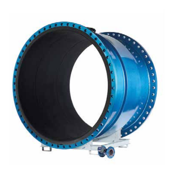
Sensors PRESSURE TAP The MUT2200EL sensor can be optionally supplied with a 1/8 ”GAS pressure plug to which a pressure transducer can be connected. The pressure transducer can be supplied by Euromag on request, and it will be integrated into the converter, or a third-party sensor can be used. -
Page 36: Insertion Meters
Where R is the radius of the passage section and D the internal diameter of the same. velocità assiale media v @ 1/8 Di = average axial speed Fig. 57 Operating principle 36 / 54 36 / 54 EUROMAG | SENSORS | Ed. 04/2019... -
Page 37: General Installation Requirements
Any damage to the measuring head could compromise the meter and its performance. • Any physical damage to the sensor probe will void the warranty. EUROMAG | SENSORS | Ed. 04/2019 37 / 54 37 / 54... -
Page 38: Alignment Of The Electrodes In Relation To The Flow
Misaligned electrodes Fig. 61 It is essential to carefully position the electrodes in relation to the direction of the pipe. Rotate to adjust the alignment of electrodes Fig. 62 38 / 54 38 / 54 EUROMAG | SENSORS | Ed. 04/2019... -
Page 39: Mut1222
In any case, the installation, assembly, and disassembly of the sensor must be carried out exclusively by expert and trained personnel. EUROMAG | SENSORS | Ed. 04/2019 39 / 54 39 / 54... -
Page 40: Calculation Of The Insertion Depth
M 1 =L - S - Where: » D = Flowmeter length according to the table of Fig. 63 » = Internal pipe diameter » = Thickness of the pipe, including possible coating 40 / 54 40 / 54 EUROMAG | SENSORS | Ed. 04/2019... -
Page 41: Installation Of The Sensor
Use PTFE tape to ensure The alignment precision the tightness of the thread. must be within ±2°. Fig. 68 Fig. 69 Fig. 70 Fig. 71 EUROMAG | SENSORS | Ed. 04/2019 41 / 54 41 / 54... -
Page 42: Installation On Non-Metallic Pipes Using A Saddle Bracket
1” bracket Gasket Fig. 72 Fig. 73 Fig. 74 7.3.5 Flowmeter grounding GROUNDING CONNECTION GROUNDING CONNECTION BOLT BOLT Grounding rod Grounding rod Fig. 75 Grounding 42 / 54 42 / 54 EUROMAG | SENSORS | Ed. 04/2019... -
Page 43: Mut2660
AISI304 Protection class - Separate IP68 Ex mb IIC T6...T4 Gb Sensor body Ottone ATEX/IECEx (only Separate) Ex mb IIIC T85°C...T135°C Db O-Ring -20°C ≤ Ta ≤ +60°C EUROMAG | SENSORS | Ed. 04/2019 43 / 54 43 / 54... -
Page 44: Calculation Of The Insertion Depth
In order to precisely set the insertion depth, it is possible to use the control value M: M=L - S - Where: » D = Flowmeter length = 367mm » = Internal pipe diameter = Thickness of the pipe, including possible coating » 44 / 54 44 / 54 EUROMAG | SENSORS | Ed. 04/2019... -
Page 45: Installation Of The Sensor
(with an accuracy of ± sensor in place. measuring head. 2°) and the insertion depth. Fig. 80 Fig. 81 Fig. 82 Fig. 83 EUROMAG | SENSORS | Ed. 04/2019 45 / 54 45 / 54... -
Page 46: Flowmeter Grounding
Sensors 7.4.4 Flowmeter grounding ROUNDING CONNECTION BOLT Grounding rod Fig. 84 Grounding 46 / 54 46 / 54 EUROMAG | SENSORS | Ed. 04/2019... -
Page 47: Mut2770
NOTE: The supply of the flowmeter includes a flanged sleeve that has to be installed on the pipe after cutting it to the right size. Size DN Range Mounting sleeve 100…500 600…1100 1200…1600 1700…2100 2200…2500 EUROMAG | SENSORS | Ed. 04/2019 47 / 54 47 / 54... -
Page 48: Calculation Of The Insertion Depth
M=L i - S - Where: » D = Sub-flange length of the flowmeter » = Internal pipe diameter = Thickness of the pipe, including possible coating » 48 / 54 48 / 54 EUROMAG | SENSORS | Ed. 04/2019... -
Page 49: Installation Of The Sensor
O-Ring Insert the sensor in the flanged 66.04x5.33 sleeve, aligning the holes. O-Ring 66.04x5.33 O-Ring O-Ring O-Ring 66.04x5.33 66.04x5.33 66.04x5.33 Fig. 89 Fig. 90 Fig. 91 EUROMAG | SENSORS | Ed. 04/2019 49 / 54 49 / 54... -
Page 50: Flowmeter Grounding
CLEANING OF EBONITE COATINGS: Cleaning and degreasing organic coatings is a delicate matter. In the case of ebonite-coated Euromag flowmeters, please avoid any acid solution containing HF (hydrofluoric acid) in any concentration. The basic solution, such as NaOH, can be used, but only at room temperature. Normal soap is recommended for removing grease and oil. - Page 51 The “repair request” form shown below on page 52 must be photocopied, filled in, and attached to the device that needs to be checked/repaired by our customer service. EUROMAG | SENSORS | Ed. 04/2019 51 / 54 51 / 54...
- Page 52 Sensors 52 / 54 52 / 54 EUROMAG | SENSORS | Ed. 04/2019...
- Page 53 Unauthorized disposal of the product by the user results in the application of the administrative sanctions provided for by applicable law. EUROMAG | SENSORS | Ed. 04/2019 53 / 54 53 / 54...
- Page 54 EUROMAG INTERNATIONAL Srl Via Della Tecnica, 20 - 35035 Mestrino (PD) - ITALY Tel. +39/049 9005064 - Fax. +39/049 9007764 euromag@euromag.com - www.euromag.com ENGLISH TD 217-1-ENG...
Need help?
Do you have a question about the MUT2200EL and is the answer not in the manual?
Questions and answers
where is the lithium battery located