
Related Manuals for Laski FZ 500/27


Summary of Contents for Laski FZ 500/27
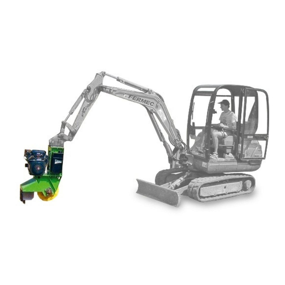
- Page 1 O P E R A T I N G I N S T R U C T I O N S SUSPENSION STUMP CUTTER FZ 500/27 FZ 500/38 FZ 500 H Version 03.2020...
- Page 2 It is very important for you and your work safety to understand all instructions given in this manual. The firm Laski, s.r.o. does not bear any responsibility for any claims resulting from disobedience to the instructions given in this manual.
-
Page 3: Ec Conformity Declaration
EC CONFORMITY DECLARATION... -
Page 8: Table Of Contents
Obsah F o r e w o r d ......... . . 2 E C C O N F O R M I T Y D E C L A R A T I O N . - Page 9 T e c h n i c a l P a r a m e t e r s ......2 8 M o d i f i c a t i o n w i t h h y d r o m o t o r .
-
Page 10: P R O D U C T I D E N T I F I C A T I O
Product Identification Our product is identified with its serial number stamped both on the type plate and on the chassis. Further on the combustion engine installed on our machine is identified with its separate type plate. Upon take-over of the product we recommend you to fill required data in the following form concerning the given product and your dealer. -
Page 11: W O R K S A F E T Y I N S T R U C T I O N
Work Safety Instructions Utilisation This suspension cutter is designed for suspension on a hydraulic jib of building machines with relevant fixing devices and for cutting a stump with its above-ground part and its under-ground part in a max. depth of 20 cm under the ground level. While working the cutter must be in a vertical position or in an angle of +/-30 to its vertical axle. - Page 12 (especially squeezing hazards at jib motion) - having started the cutter the operator is not allowed to leave his cab of a building machine and he should be permanently watching the cutting operation - the operator should avoid any activity which could bring hazards for himself and other persons - while handling the cutter, especially after its start, avoid its contact with the building machine.
-
Page 13: W O R K S A F E T Y S Y M B O L
Some parts of the machine can be extremely hot while in operation. To avoid any burn risks do not touch these parts when the engine is still running or when having just stopped the engine. Do not touch live wires while the machine is still in use. Do not let the engine running in high speed unreasonably. - Page 14 Read this Always follow the Warning! Electric Before putting out of operating manual manual while current is present operation fix the before use. maintaining, servicing or on the machine. cutter in the repairing the machine supporting frame. and take the switch key out of ignition.
- Page 15 Warning! Lower Warning! The Warning! Rejected Warning! Close all extremities injury cutting head is objects hazard. Keep guards before hazard. running out. away. starting the machine.
-
Page 16: T R A N S P O R T O F P R O D U C
Transport of Product This product is delivered completely mounted, fixed in a supporting frame and attached to a wooden pallet. The supporting frame is usually bolted or fixed with a binding band to the pallet. While handling you may use a lift truck or a crane (suspension in the given lashing points only). -
Page 17: P R O D U C T H A N D L I N G U P O N D E L I V E R
Product Handling upon Delivery Upon delivery unload the machine from the transport pallet as follows: Put the pallet aside on a flat and firm surface. Remove transport protective wrapping. Cut the binding band carefully or loosen the fixing bolts. Be careful, the band is tightened up and after cutting its both ends may shot out. -
Page 18: C O N T R O L
CAUTION!!! Having turned the engine off the cutting head is freely running out. Any head braking is strictly forbidden. Controls The stump cutter can be operated by means of controls on the remote control box and aside on the engine. Auxiliary view of engine controls Remote control box - choke... - Page 19 possible thanks to technical parameters of a building machine. In this case the supporting frame may remain fixed on the pallet. The cutter must be transported always being fixed in the supporting frame. After loading fix the supporting frame properly on the loading surface. For fixing use lash eyes for such purpose welded on the frame.
-
Page 20: B E F O R E O P E R A T I O
Before Operation Before the first putting into operation check up the machine for contingent damages and completeness after transport and storage. Check wrapping for contingent oily spots. In such case check oil charges. Check the engine oil level with a dipstick and refill if necessary. The oil level must be between both marks (MIN and MAX). -
Page 21: C O U P L I N G / U N C O U P L I N
Coupling/uncoupling The cutter should be coupled to a building machine with min. carrying capacity of 300 kg in the whole range of its hydraulic jib. The cutter should be equipped with a bolted suspension joint. Its bolts must be tightened properly. -
Page 22: C H E C K S B E F O R E S T A R
Checks before Start Before putting into operation check up the machine for completeness. Check up all bolted joints, especially on the cutting head. Check up all cutting blades for completeness. If one of them is damaged change it immediately. It is not allowed to operate the cutter with damaged guards or cutting head. Dipstick Air filter Fuel tank... - Page 23 Do not lean the cutter against the ground or against any other object. Check the engine oil level with a dipstick and refill if necessary. The oil level must be between both marks (MIN and MAX). Check tightening of bolted joints, especially rotating parts and completeness of other parts.
-
Page 24: P U T T I N G I N T O O P E R A T I O
Putting into Operation Start the cuter only after its proper coupling to the hydraulic jib, the cutting head should not be in contact with any object and there are no persons or animals within reach. Connect the remote control. Install the remote control leads properly on the hydraulic jib so that the wires are protected against any damage. -
Page 25: E M E R G E N C Y S I T U A T I O N
push the STOP button Be aware, the cutting head runs out, keep away until it stops. Emergency Situations The red STOP button for emergency cases is located on the remote control box. If any such situation occurs, push the button immediately. Having pushed this button the cutting head runs out. -
Page 26: N O I S E A N D V I B R A T I O N
Set the building machine in a stabile position within reach of the given stump. Be aware of rejected objects when cutting and avoid any hazards for other persons, animals and property. It is also not allowed to use the cutter if the operator of a building machine has no view to the cutting blades. -
Page 27: T E C H N I C A L D E S C R I P T I O
While working persons operating this machine are obliged to use protective aids active against noise in level of N 90 dB. Technical Description The suspension stump cutter is built in the split bolted chassis consisting of its carrying frame used for coupling to a hydraulic jib. Holes for a suspension fixing device are on a plate on the upper part of the frame. -
Page 28: T E C H N I C A L P A R A M E T E R
Technical Parameters FZ 500/27 FZ 500/38 FZ 500H Overall length: Overall width: Overall height: 1260 1000 Cutting performance: .hod cca 0,6 Cutting bite Cutting head diameter: Under ground Above ground according to vehicle Number of blades: Drive belts blades - 3x... -
Page 29: M O D I F I C A T I O N W I T H H Y D R O M O T O
ENGINE Type: hydromotor KOHLER COMMAND CH 740 CH 980 Power output: 18,6 26,1 20,8 Operating speed: 3600 Lubrication: forced ° Max. gradient Engine oil: SAE 10W-40 Oil charge: 2,85 Fuel: unleaded petrol (NATURAL 95) Fuel tank capacity: Electric installation Battery Ignition: magnetoelectric Displacement hydraulic... -
Page 30: D I A G R A M O F T H E H Y D R A U L I C C I R C U I T F
Diagram of the hydraulic circuit FZ 500H V a r i a n t – A recommended layout diagram for the machines equipped with separate dripping line going directly into the digger hydraulic tank. Variant – B A layout diagram for the diggers equipped with 2- hose hydraulics on the machine jib only. -
Page 31: M A I N T E N A N C
Maintenance Any servicing of the cutter can be carried out by authorised persons only. Check up the machine for completeness and its general condition. Check up the V-belts for tightness and wear. Keep regular intervals for lubrication of cutting head bearings. Tension bolts of belt gearing Pay special attention to routine maintenance of the battery. - Page 32 Service life of the battery installed in the machine is rather limited. It is usually 3-4 years and after this period the battery should be replaced by a new one. Oil change The first oil change after 100 working hours and next changes every 100 hrs. Change the oil always when the engine is turned off and still warm.
-
Page 33: B L A D E S C H A N G
Remove the used blades and fit new ones Tighten up the bolts Use torque wrench - torque value of 105 Nm Use always original spare parts and LASKI bolts (10) only At this change proceed carefully and avoid any accident Secure the machine against possible rollover... -
Page 34: T R O U B L E S H O O T I N
Troubleshooting Failure Cause Remedy Engine does not start Discharged battery Recharge battery Broken lead Check up wiring SERVICE No plug sparking Clean spark plug Change spark plug Change element Fouled filter Refill fuel Lack of fuel Low engine oil level Refill oil Note: The note "SERVICE"... - Page 35 Damage of the machine caused by faulty handling, maintenance or overloading. This warranty does not cover faults resulted from damages caused by the user. This warranty does not cover parts being subject to ordinary wear and tear. ...
- Page 36 S e r v i c e R e p o r t...
Need help?
Do you have a question about the FZ 500/27 and is the answer not in the manual?
Questions and answers