Table of Contents
Advertisement
Advertisement
Table of Contents

Related Manuals for Laski F-360 SW


Summary of Contents for Laski F-360 SW
-
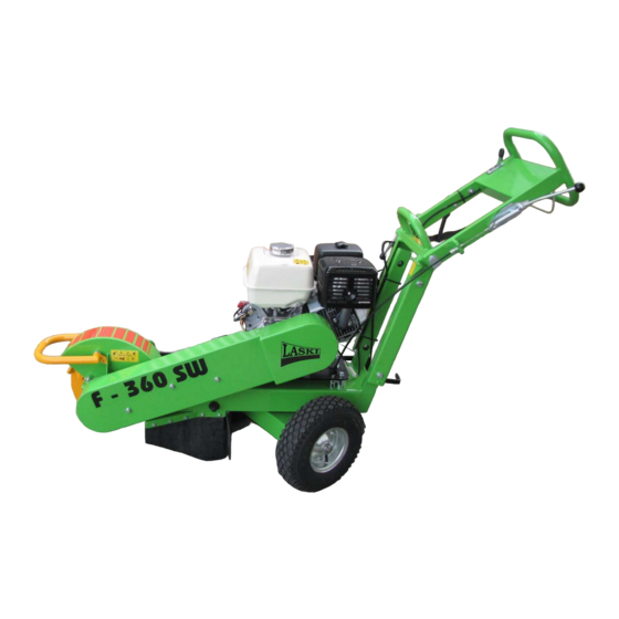
Page 1: Operating Instructions
OPERATING INSTRUCTIONS „Orig. version: 02. 2015... -
Page 2: Foreword
It is very important for you and your work safety to understand all instructions given in this manual. The firm Laski s.r.o. does not bear any responsibility for any claims resulting from disobedience to the instructions given in this manual. -
Page 5: Table Of Contents
Contents OPERATING INSTRUCTIONS ..........1 Foreword ......................2 Product Identification .................... 6 Work Safety Instructions ..................7 Utilisation ........................ 7 Not Allowed Use ....................7 Generally ......................... 7 Work Safety Symbols ..................10 Transport of Product/Handling ................12 Lifting ........................ 13 Unloading from transport pallet ................ -
Page 6: Product Identification
Product Identification Our product is identified with its serial number stamped both on the type plate and on the chassis. In addition to that, you can find a separate type plate on the engine block. Upon take-over of the product we recommend you to fill the required data in the following form concerning the given product and your dealer Type of product: …………………………………………………………………... -
Page 7: Work Safety Instructions
Work Safety Instructions Utilisation This product is designed for cutting a stump with its above-ground part up to +200 mm and its under-ground part in a max. depth of -120 mm under the ground level. Recommended stump diameter: up to 300 mm. This stump cutter is designed for control and operation by one attendant (operator) only. - Page 8 Keep this machine beyond children's and unauthorised persons' reach. Avoid their presence while working. Observe the working area. If any person, children or animals approach while cutting, then stop working immediately. Before working learn all functions of individual controls and safety elements and carry out functional checks before any use.
- Page 9 Do not use or attempt to start the stump cutter without the cutter guards, engine covers and access covers securely in place. Failure to do so may result in personal injury or loss of life Keep the given intervals for checks of bolted joints. Keep clean the cooling air holes and the fuel tank space.
-
Page 10: Work Safety Symbols
Work Safety Symbols Work Safety Symbols Work Safety Symbols Work Safety Symbols This article introduces work safety symbols (pictographs) used on this machine. Under the given pos. number there is their location on the machine. These work safety symbols warn the operator against risks connected with the machine use. Your respect to the symbol meaning is a precondition for your work safety. - Page 11 Warning! Fuel is Warning! Hot parts Warning! Rotating Lashing points. flammable liquid - of exhaust manifold parts – pull-in keep the machine hazard. beyond the reach of naked flames. Warning! Lower Warning! Cutting Warning! Keep away Warning! Keep Warning! Close all extremities injury head runs out.
-
Page 12: Transport Of Product/Handling
Transport of Product/Handling Transport of Product/Handling Transport of Product/Handling Transport of Product/Handling This product is delivered completely mounted, with all guards and safety elements, controls, engine oil charge and necessary accessories ready to work This product is attached to a wooden pallet. While handling, you may use a lift truck or a crane (suspension in the given lashing points only) –... -
Page 13: Lifting
The manufacturer delivers the machine shrink-wrapped. The protective foil protects the machine against weather effects but in no case against mechanical damage, fall etc. The protective foil is recyclable; dispose it according to valid local regulations. While putting the machine aside (e.g. at reloading), we recommend to place it under a shelter to protect the foil against direct sunshine. -
Page 14: Unloading From Transport Pallet
For crane handling, use a crane (tackle) with its minimum carrying capacity of 200 kg. Unloading from transport pallet Unloading from transport pallet Unloading from transport pallet Unloading from transport pallet After delivery unload the machine from the transport pallet as follows: Cut the binding bands carefully. - Page 15 guards are fixed, bolted down and solid, only the guard over the exhaust manifold is perforated. At standstill the cutting head is covered with a pipe framing protecting the cutting head and its blades against hitting. Under the grip there is the "dead-man lever" installed which has to be pushed down while working.
-
Page 16: Attendant's Place
Attendant's Place Attendant's Place Attendant's Place Attendant's Place While working, the attendant should stand behind the grip (see fig.), holding it with both hands and with both feet standing on a flat and firm base. All working motions should be continuous and uniform. It is strictly forbidden to stand aside or to hold the grip with one hand only Right attendant's position behind the grip... -
Page 17: Controls
Controls Controls Controls Controls The stump cutter can be operated by means of controls on the grip and aside on the engine. 1 – dead-man lever 6 – adjustment lever for grip 2 – speed regulator and engine-stop positioning lever 7 –... -
Page 18: Noise And Vibrations
Noise and Vibrations Operation of this stump cutter brings following emissions: F 360 SW F 360 SW/11 F 360 SW/14 Noise L at idle (dB) 90,0 91,6 Sound power L (dB): 103,3 104,4 Vibrations a (m.s All measurements taken in accordance with: EN ISO 11201 EN ISO 3744 Measurements of vibrations:... -
Page 19: Putting Into Operation
Check up the cutting blades for wear and completeness. If one of them s damaged, change both opposite blades immediately. If different abrasion occurs, change both opposite blades on account of balance of the cutting head – unwanted vibrations may damage the machine. Fill the given fuel into the tank, min. -
Page 20: Transport, Handling And Storage
Pull the starting cord. For the first start it is necessary to pull the cord several times to suck the fuel into the engine carburettor. Pull the starting cord quite rapidly. Having started, raise the speed gradually by means of the speed regulator and close the choke. - Page 21 If using a ramp for loading or unloading then it must be steady enough with no slippery surface. Such a ramp could be with a max. gradient of 20%. In case of this ramp gradient it should be preferable if other two persons will assist to you with such handling.
-
Page 22: Use
Transport the machine to another site with the engine off by pushing or towing. Keep all work safety instructions to avoid any risks of injury. When going to another working site always ascend and descend slopes very carefully and with the cutting head up the hill. Be careful when going down the hill. - Page 23 If there are too many chips gathered behind the cutting head, turn off the machine, wait until the head stops and remove the chips so that you can always observe the head while cutting. While the cutting head is still running, it is strictly forbidden to enter the space of the running head with extremities or with any tools (sticks, rake etc.) RECOMMENDATIONS...
-
Page 24: Putting Out Of Operation
Stepwise cutting from particular sides Simple drawing of individual cuts Side swinging on released swivel base Putting out of Operation Putting out of Operation Putting out of Operation Putting out of Operation When having finished the work or for a break: reduce the engine speed –... -
Page 25: Emergency Situations
while turning the machine off, avoid any contact of the cutting head when resting on the ground or on any hard objects (stones, iron etc.) – use always its supporting leg. Having turned the centrifugal clutch off, the cutting head is freely turning out. -
Page 26: Technical Parameters
One of the blades is always a straight tool (11) and the other one is a bent tool (12). The straight tools (11) in adjacent pairs are always fixed on the opposite sides of the cutting head (8). The cutting head (8) is powered by the driving unit (4) by means of the V-belts (15). -
Page 27: Maintenance
with blades Number of blades: Bite width V-belt 3x AVX 13 x 1700 La ENGINE Type KOHLER CH 440 HONDA GX 390 four-stroke, air-cooled four-stroke, air-cooled Power output HP/ kW 14/10,4 at 3600 rpm 11,7/8,7 at 3600 rpm Engine oil charge Fuel tank capacity Max. - Page 28 Keep the given intervals for checks of bolted joints. After every working shift check up tightening of bolted joints, particularly rotating parts and completeness of other parts, such as fixation of blades and subgroups on framing. Any servicing is allowed to be done at standstill only. Provide your machine shops with suitable extinguishers and first-aid kits to be accessible anytime at fire risk.
- Page 29 new oil of proper viscosity through the filler neck and then screw up the filler plug. In case of any failure in the lubrication system the engine stops Air Filter The air filter with two filter elements provides maximum protection against mechanic impurities and keeps continuous air flow into the fuel system.
- Page 30 Electric Protect all wires against contact with oil products. Keep all Installation elements clean and avoid any damage of wires – short circuit risk. All connections must have clean and proper contact surfaces to avoid intermediate resistance at a wrong contact point.
-
Page 31: Replacement Of Blades And Regrinding
Tighten up the bolts Use torque wrench - torque value of 105 Nm Use always original spare parts and the LASKI bolts (10) only At this change proceed carefully and avoid any work accident Secure the machine against possible rollover... - Page 32 While tightening the belts proceed as follows: Check up tension of new belts after first 5 service hours and afterwards always in intervals of 50 hours. Excessive slipping will wear the belts and the pulleys out prematurely. Excessive tension reduces belt life essentially. It brings also negative impact on optimal alignment of pulleys.
- Page 33 Attachment of the engine to the frame, F 460 Attachment of the engine to the frame, F 360 Loosen four fixing bolts on the engine (1 - 4x) by 0,5 – 1 turn to let the engine slide on the frame. Loosen the locking nuts on the stretching bolts (2 - 2x) and move the engine in its slot holes as necessary.
-
Page 34: Failures And Troubleshooting
Belts as to modification Finger pressure F (N) Slack p (mm) F 360 23,5 Replace the belts guards Failures and Troubleshooting Failures and Troubleshooting Failures and Troubleshooting Failures and Troubleshooting Remedy Failure Cause Engine does Speed regulator lever Set proper speed not start in STOP position Ignition breaker in "0"... -
Page 35: Waste Disposal
transmission to Burnt V-belts Replacement cutting head Worn (extended) V- Replacement belts Insufficient Damaged blades Replacement cutting head Blunt or worn blades Replace or regrind power blades Opposite blades should be replaced always together service Wire control out of Adjustment tune Note: The note "SERVICE"... - Page 36 Paper - secondary waste recovery, burning Metals - secondary waste recovery Other materials are municipal waste and should be disposed in accordance with laws and regulations valid in the given country.
-
Page 37: Warranty
Warranty The manufacturer provides warranty on this product for a period as stated in the enclosed Letter of Indemnity. This warranty period begins upon delivery to the customer. This warranty covers all failures resulted from faulty assembly, manufacture and materials. The manufacturer bears no responsibility for damages resulted from user's wrong usage, such as: •... -
Page 38: Service Report
Service Report... - Page 39 Service Report...
- Page 40 Service Report...
Need help?
Do you have a question about the F-360 SW and is the answer not in the manual?
Questions and answers