Table of Contents
Advertisement
Quick Links
BABBITT
INTERNATIONAL, INC.
L
S
8
0
0
0
/
2
L
L
S
8
0
0
0
/
2
L
O
W
N
E
R
S
O
W
N
E
R
S
♦
♦
I
N
S
T
A
L
L
I
N
S
T
A
L
L
♦
♦
C
A
L
I
B
R
A
C
A
L
I
B
R
A
♦
♦
T
R
O
U
B
L
T
R
O
U
B
L
♦
W
A
R
R
A
N
W
A
R
R
A
N
E
V
E
L
S
W
I
T
C
E
V
E
L
S
W
I
T
C
M
A
N
U
A
L
M
A
N
U
A
L
A
T
I
O
N
A
T
I
O
N
T
I
O
N
T
I
O
N
E
S
H
O
O
T
I
N
G
E
S
H
O
O
T
I
N
G
T
Y
T
Y
H
H
P.O. Box 70094
Houston, Texas 77270
(713) 467-4438
Advertisement
Table of Contents

Related Manuals for BABBITT LS8000/2


Summary of Contents for BABBITT LS8000/2
- Page 1 ♦ ♦ ♦ ♦ ♦ ♦ ♦ BABBITT P.O. Box 70094 Houston, Texas 77270 INTERNATIONAL, INC. (713) 467-4438...
-
Page 2: Table Of Contents
TABLE OF CONTENTS Page 1. Description -------------------------------------------------------------- 1 A. General Description ----------------------------------- 1 B. Specifications -------------------------------------------- 2 C. Ordering Information ----------------------------------- 2 2. Theory of Operation -------------------------------------------- 3 3. Installation-------------------------------------------------------------- 3 A. Inspection ----------------------------------------------------- 3 B. Physical Installation -------------------------------------------- 3 C. -
Page 3: Description
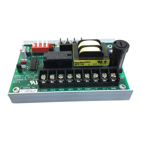
1. DESCRIPTION A. General Description The LS8000/2 dual point level switch is designed to sense material at two points in a tank, hopper or sump. The unit consists of a receiver which may be remote mounted from the sensing probe(s). -
Page 4: Specifications
B. Specifications Electrical Power: 115 VAC (±15%) 50/60 Hz. 3 watts, standard. (12 VDC, 24 VDC or 230 VAC optional) Output: 3 relays, each with 1 form C contact, SPDT, 10 amp resistive at 115 vac, 8 amp at 220 VAC, 5 amp at 30 VDC Fuse: On board, 250 mA... -
Page 5: Theory Of Operation
4. A plastic snaptrack to mount the receiver card. B. Physical Installation of Transmitter Module and Probe 1) The LS8000/2 is installed into the vessel wall using a ¾” NPT connection. This can be either a threaded coupling or a tapped entry such as a flange. -
Page 14: Installing The Receiver
FSH or FSL marking on the LS8000/2 receiver card. B. Setting “POR” and “LATCH” Dip Switches Switches “POR” and “LATCH” are 2 of the 4 dip switches on the LS8000/2 sensing card. “LATCH” selects automatic fill or automatic empty. -
Page 15: Calibrate The Low Setpoint
If the unit should lose power, and the level is between the setpoints, the LS8000/2 can not “remember” if it was filling or emptying at the time of power loss. -
Page 16: Maintenance And Troubleshooting
No routine maintenance is required other than to keep the interior of the unit clean and free of dirt, moisture and other contaminants. The LS8000/2 consists of three main sub-assemblies. These are the enclosure with the antenna probe, the transmitter module and the receiver card. The following troubleshooting guide will assist in determining how to correct most of the problems, which may occur in the field. -
Page 17: Warranty
6. WARRANTY All components of the LS8000/2 are warranted to be free from defects in material and workmanship for a period of two years from the date of purchase. This warranty applies to general purchaser and to components installed, serviced and operated according to instructions.
Need help?
Do you have a question about the LS8000/2 and is the answer not in the manual?
Questions and answers