Table of Contents
Advertisement
Advertisement
Table of Contents

Related Manuals for Stoneridge Veeder-Root 2400 Series


Summary of Contents for Stoneridge Veeder-Root 2400 Series
- Page 1 2400 User Manual Copyright © 2004 Stoneridge Electronics Ltd...
-
Page 2: I M P O R T A N T I N F O R M A T I O N
The tachograph drawer is not capable of supporting loads in the open position. The EMC performance of the Veeder-Root 2400 tachograph unit complies with the requirements of EU Commission Directive 95/54/EC. 2400 User Manual Copyright © 2004 Stoneridge Electronics Ltd... -
Page 3: Table Of Contents
6.0 STATUS SETTING .............................14 6.1 Setting the Driver Duty ...............................14 6.2 Setting the Crew Duty..............................14 7.0 CHART RECORDING WITH THE VEHICLE STATIONARY AND THE IGNITION OFF......14 8.0 FILLING IN TACHOGRAPH CHARTS .......................15 2400 User Manual Copyright © 2004 Stoneridge Electronics Ltd... - Page 4 Figure 14 Fields to be Completed at the Start of a Shift ....................25 Figure 15 Fields to be Completed at the End of a Shift ....................26 Figure 16 View of the Reverse Side of the Tachograph Chart ..................27 Veeder-Root Service Network..............................28 2400 User Manual Copyright © 2004 Stoneridge Electronics Ltd...
-
Page 5: 2400 Series Tachograph (With Display)
The 2400 series tachograph may be installed as a component of a wider system, for example an instrument cluster. The information that is shown on the tachograph’s display, that is speed, odometer and time would thus also be displayed elsewhere on the vehicle’s instrument cluster. 2400 User Manual Copyright © 2004 Stoneridge Electronics Ltd... -
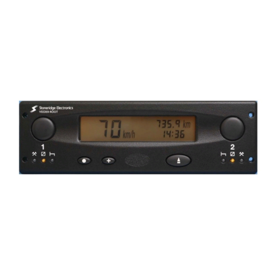
Page 6: Figure 1 Illustration Of The Controls
PUSH here Drawer Rest ‘Other Work’ ‘Other Work’ Advance Change for Drawer Eject LED (see LED (see Button Button Latch/Unlatch Button page 7) Page 7) Figure 1 Illustration of the Controls 2400 User Manual Copyright © 2004 Stoneridge Electronics Ltd... -
Page 7: Description Of The Controls
In some circumstances, the LEDs will flash in a distinguishable pattern to indicate that the tachograph is performing actions other than chart recording (for example aligning the chart or charts within the unit) as shown in Figure 2. 2400 User Manual Copyright © 2004 Stoneridge Electronics Ltd... -
Page 8: Mode Change Push-Button
Figure 5. After the drawer has been opened, the LEDs revert to their previously selected status indicating the current driver duty (or duties if the tachograph is arranged for two driver operation). 2400 User Manual Copyright © 2004 Stoneridge Electronics Ltd... -
Page 9: Display
The left-hand side of the display indicates the current speed of the vehicle, expressed in kilometres per hour (km/h). Figure 6 Display in NORMAL Mode (page 21) Figure 7 Display in TRIP Mode (page 21) 2400 User Manual Copyright © 2004 Stoneridge Electronics Ltd... -
Page 10: Adjusting The Time Setting
In a unit with a battery-backed clock the universal time is stored by the unit when power is removed. The driver can only adjust an OFFSET around that time. The ranges of the offsets are –23h 59m to +23h 59m. 2400 User Manual Copyright © 2004 Stoneridge Electronics Ltd... -
Page 11: Mode Setting
The DTC display must be enabled in the 2400 tachograph for this mode to be possible. To enter the DTC Value Display Mode, press the ( ) and ( ) buttons simultaneously. The screen of the tachograph would appear as shown in Figure 9. Figure 9 Display in DTC Value Mode (page 21) 2400 User Manual Copyright © 2004 Stoneridge Electronics Ltd... -
Page 12: Dtc Time And Date Display Mode
It is not necessary to fit the Crew chart when the tachograph is being used for single Driver operation. However, after the Driver chart is installed and the drawer is closed, the Crew LEDs may indicate that a chart is missing (as described above). 2400 User Manual Copyright © 2004 Stoneridge Electronics Ltd... -
Page 13: Crew Chart Insertion
Figure 13. Locate the chart such that the pear-shaped hole in the centre of the chart locates over the corresponding pear-shaped drive spindle. Figure 13 Method of Driver Chart Insertion (page 24) 2400 User Manual Copyright © 2004 Stoneridge Electronics Ltd... -
Page 14: Chart Removal
7.0 CHART RECORDING WITH THE VEHICLE STATIONARY AND THE IGNITION OFF If all of the following conditions are present, • Driver duty (and if appropriate, Crew duty) set to Rest. • Zero speed. 2400 User Manual Copyright © 2004 Stoneridge Electronics Ltd... -
Page 15: Filling In Tachograph Charts
Note: Do not press too hard when drawing a manual trace, in order to avoid marking the front of the chart. The manual trace runs anti-clockwise with respect to time, which is the reverse of the direction that the automatic trace runs. 2400 User Manual Copyright © 2004 Stoneridge Electronics Ltd... -
Page 16: Recording Vehicle Changes
The tachograph drawer is NOT designed to support weight when in the open position. • When opening the Tachograph, the ONLY acceptable place to push the drawer is identified on Figure 4. 2400 User Manual Copyright © 2004 Stoneridge Electronics Ltd... -
Page 17: Warning Codes
Reset tachograph and retest 9063 Cam Error Cam motor or opto failure. Reset tachograph and retest. 9064 Chart Table Error Chart table motor or opto failure. Check charts inserted correctly. Reset tachograph and retest. 2400 User Manual Copyright © 2004 Stoneridge Electronics Ltd... - Page 18 No Driver Chart Present Drawer closed with no driver chart Insert driver chart present. 9052 No Crew Chart Present Drawer closed with no crew chart Insert crew chart if required. present. 2400 User Manual Copyright © 2004 Stoneridge Electronics Ltd...
- Page 19 Figure 3: LED Sequence When Operator Action Figure 2: LED Sequence When Tachograph Carrying out Automatic Functions. Required. 2400 User Manual Copyright © 2004 Stoneridge Electronics Ltd...
- Page 20 Figure 5: Opening of the Tachograph Drawer. Figure 4: Drawer Ejection, Position of the Safe ‘Push’ Position. 2400 User Manual Copyright © 2004 Stoneridge Electronics Ltd...
-
Page 21: Figure 6 Display In Normal Mode
Figure 8: Display in Clock Adjust Mode. Figure 6: Display in NORMAL Mode. Figure 9: Display in DTC Value Mode. Figure 7: Display in TRIP Mode. 2400 User Manual Copyright © 2004 Stoneridge Electronics Ltd... -
Page 22: Figure 10 Display In Dtc Time And Date Mode
Figure 11: Status of LEDs When Driver Chart Missing (Alternating On and Off). Figure 10: Display in DTC Time and Date Mode. 2400 User Manual Copyright © 2004 Stoneridge Electronics Ltd... -
Page 23: Figure 12 Method Of Crew Chart Insertion
Drawer Slot. Figure 12: Method of Crew Chart Insertion. 2400 User Manual Copyright © 2004 Stoneridge Electronics Ltd... -
Page 24: Figure 13 Method Of Driver Chart Insertion
Driver chart location. Figure 13: Method of Driver Chart Insertion. 2400 User Manual Copyright © 2004 Stoneridge Electronics Ltd... -
Page 25: Figure 14 Fields To Be Completed At The Start Of A Shift
Driver’s name. Place of Departure. Vehicle Registration. Departure date. Departure odometer reading. Figure 14: Fields to be Completed at the Start of a Shift. 2400 User Manual Copyright © 2004 Stoneridge Electronics Ltd... -
Page 26: Figure 15 Fields To Be Completed At The End Of A Shift
Location at Shift End. Date at Shift End. Odometer reading at Shift End. Distance travelled (difference between odometer readings). Figure 15: Fields to be Completed at the End of a Shift. 2400 User Manual Copyright © 2004 Stoneridge Electronics Ltd... -
Page 27: Figure 16 View Of The Reverse Side Of The Tachograph Chart
Vehicle Registration. Start Time at New vehicle. End Odometer Reading. Start Odometer Reading. Trip Distance. Figure 16: View of the Reverse Side of the Tachograph Chart. 2400 User Manual Copyright © 2004 Stoneridge Electronics Ltd... -
Page 28: Veeder-Root Service Network
Council Regulation (EEC) No. 3821/85 Article 16) and ensures that any work done is carried out only by properly trained specialist staff. A full list of Stoneridge Electronics/Veeder-Root International Distributors and Service Centres is included from page 120 in the Main 2400 Tachograph User Manual (part number 5973-020 Rev 4.0)
Need help?
Do you have a question about the Veeder-Root 2400 Series and is the answer not in the manual?
Questions and answers
How much is one?
The price of the Stoneridge Veeder-Root 2400 Series tachograph is £79.00 or Best Offer.
This answer is automatically generated