Sign In
Upload
Manuals
Brands
Stoneridge Manuals
Data Loggers
Veeder-Root 2400 Series
Stoneridge Veeder-Root 2400 Series Data Manuals
Manuals and User Guides for Stoneridge Veeder-Root 2400 Series Data. We have
1
Stoneridge Veeder-Root 2400 Series Data manual available for free PDF download: User Manual
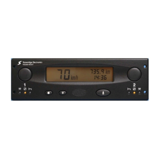
Stoneridge Veeder-Root 2400 Series User Manual (28 pages)
Tachograph
Brand:
Stoneridge
| Category:
Data Loggers
| Size: 0 MB
Table of Contents
I M P O R T a N T I N F O R M a T I O N
2
Table of Contents
3
Contents
3
2400 Series Tachograph (with Display)
5
2400 Tachograph with Remote Display
5
Figure 1 Illustration of the Controls
6
2 Description of the Controls
7
Driver Duty Push-Buttons
7
Leds
7
Mode Change Push-Button
8
Advance Push-Button
8
Eject Push-Button
8
Figure 2 LED Sequence When Tachograph Carrying out Automatic Functions
8
Figure 3 LED Sequence When Operator Action Required
8
Display
9
Figure 4 Drawer Ejection, Position of the Safe 'Push' Position
9
Figure 5 Opening of the Tachograph Drawer
9
3 Adjusting the Time Setting
10
Clock Setting for Units Without Real Time Clock (RTC)
10
Clock Setting for Units with Battery Backed Real Time Clock (RTC)
10
4 Mode Setting
11
Normal and Trip Modes
11
DTC Value Display Mode
11
DTC Time and Date Display Mode
12
5 Insertion and Removal of the Tachograph Chart
12
Crew Chart Insertion
13
Driver Chart Insertion
13
Chart Removal
14
6 Status Setting
14
Setting the Driver Duty
14
Setting the Crew Duty
14
7 Chart Recording with the Vehicle Stationary and the Ignition off
14
8 Filling in Tachograph Charts
15
Driver and Crew Chart Centre Fields
15
Manual Trace Indication
15
Recording Vehicle Changes
16
9 Power Down' Features
16
10 Care and Maintenance of the Tachograph
16
Cleanliness
16
Protecting the Tachograph from Damage
16
11 Warning Codes
17
12 Diagnostic Trouble Codes (Dtc)
17
Figure 6 Display in NORMAL Mode
21
Figure 7 Display in TRIP Mode
21
Figure 8 Display in Clock Adjust Mode
21
Figure 9 Display in DTC Value Mode
21
Figure 10 Display in DTC Time and Date Mode
22
Figure 11 Status of Leds When Driver Chart Missing (Alternating on and Off)
22
Figure 12 Method of Crew Chart Insertion
23
Figure 13 Method of Driver Chart Insertion
24
Figure 14 Fields to be Completed at the Start of a Shift
25
Figure 15 Fields to be Completed at the End of a Shift
26
Figure 16 View of the Reverse Side of the Tachograph Chart
27
Veeder-Root Service Network
28
Advertisement
Advertisement
Related Products
Stoneridge OPTIMO 2
Stoneridge digipostpro
Stoneridge SE5000-8
Stoneridge Categories
Measuring Instruments
Automobile Accessories
Data Loggers
Control Unit
Dash Cameras
More Stoneridge Manuals
Login
Sign In
OR
Sign in with Facebook
Sign in with Google
Upload manual
Upload from disk
Upload from URL