
Related Manuals for JSR Ultrasonics PureView Series


Summary of Contents for JSR Ultrasonics PureView Series
- Page 1 PureView Series USB Pulser Receiver ® Operator Manual PureView User Manual Version 1.3 January 2021 Copyright 2021. All Rights Reserved...
-
Page 2: Safety Advisories
PureView™ Pulser-Receiver Operator Manual This information in this document is applicable to all models in the PureView™ Pulser-Receiver Instrument series. Copyright© 2021 by Imaginant Inc. This manual is protected by United States copyright law and international treaty provisions. All rights reserved. Imaginant and PureView™ are registered trademarks of Imaginant Inc. PureView™... - Page 3 PureView™ Pulser-Receiver Operator Manual English Use the PureView instrumentation as directed by the manufacturer. If you do not use as directed, overall safety could potentially be compromised. Français /French Si les instruments PureView ne sont pas employés selon les prescriptions du fabricant, la sécurité globale peut en être affectée.
-
Page 4: Table Of Contents
PureView™ Pulser-Receiver Operator Manual Table of Contents SAFETY ADVISORIES ............................2 HARDWARE LIMITED WARRANTY ........................7 SOFTWARE LIMITED WARRANTY AND LICENSE AGREEMENT ................7 APPLICATION DISCLAIMER ..........................7 POWERING PUREVIEW INSTRUMENTS ......................7 PRODUCT PACKAGE CONTENTS ........................8 ADDITIONAL EQUIPMENT REQUIRED (CUSTOMER SUPPLIED) ................8 OVERVIEW ................................ - Page 5 PureView™ Pulser-Receiver Operator Manual USING JSR .NET CONTROL PANEL SOFTWARE ....................18 JSR .N ..................... 19 ECEIVER ONTROLS IN ONTROL ANEL Power LED ............................19 Receiver Mode ..........................19 Gain..............................19 Low Pass Filter ..........................19 High Pass Filter ..........................19 JSR .N ....................
- Page 6 PureView™ Pulser-Receiver Operator Manual Miscellaneous ..........................23 Environmental ..........................23 Page 6 Imaginant Inc.
-
Page 7: Hardware Limited Warranty
PureView™ Pulser-Receiver Operator Manual Hardware Limited Warranty Imaginant Inc. warrants that PureView instrumentation will be free from defects in materials and workmanship for a period of one year from the date of purchase. Imaginant will, at its option, repair or replace any PureView products that prove to be defective during the warranty period without charge for parts and labor. -
Page 8: Product Package Contents
PureView™ Pulser-Receiver Operator Manual Product Package Contents The following items are included in the PureView shipping box: 1. PureView Pulser-Receiver 2. USB cable, Type A to Mini-B Additional Equipment Required (Customer Supplied) 1. Computer running Windows O/S with an available USB port, preferably an enhanced-power USB port. 2. -
Page 9: Overview
PureView™ Pulser-Receiver Operator Manual Overview PureView Instruments comprise a family of Pulser-Receivers that are USB controlled and powered. various PureView models span a broad range of operating frequencies that enable a correspondingly broad range of ultrasound system applications. User control of these instruments is achieved through commands sent from a computer to the instrument via the USB interface. -
Page 10: Control Logic And Usb Interface
PureView™ Pulser-Receiver Operator Manual T/R- Through Through Select Output Amplifier/ Low Pass High Pass Attenuator Filter Filter Trig/Sync Pulser PRF Control (Energy & Damping) Pulser Voltage Control Logic Figure 1: PureView System Block Diagram Control Logic and USB Interface The USB interface and associated control logic provides control of a PureView instrument through software resident on a host computer. -
Page 11: T/R And Through Select
PureView™ Pulser-Receiver Operator Manual T/R and Through Select Selecting the “T/R” mode (also referred to as “Echo” mode) connects the T/R connector to the Receiver input. This configures the instrument for performing Transmit/Receive measurements with a single transducer. Selecting the “Through” mode connects the Through connector to the Receiver input. This configures the instrument for performing Through measurements using a transmit transducer and a separate receiving transducer. -
Page 12: Pureview Enclosure, Interface Connectors, And Status Indicators
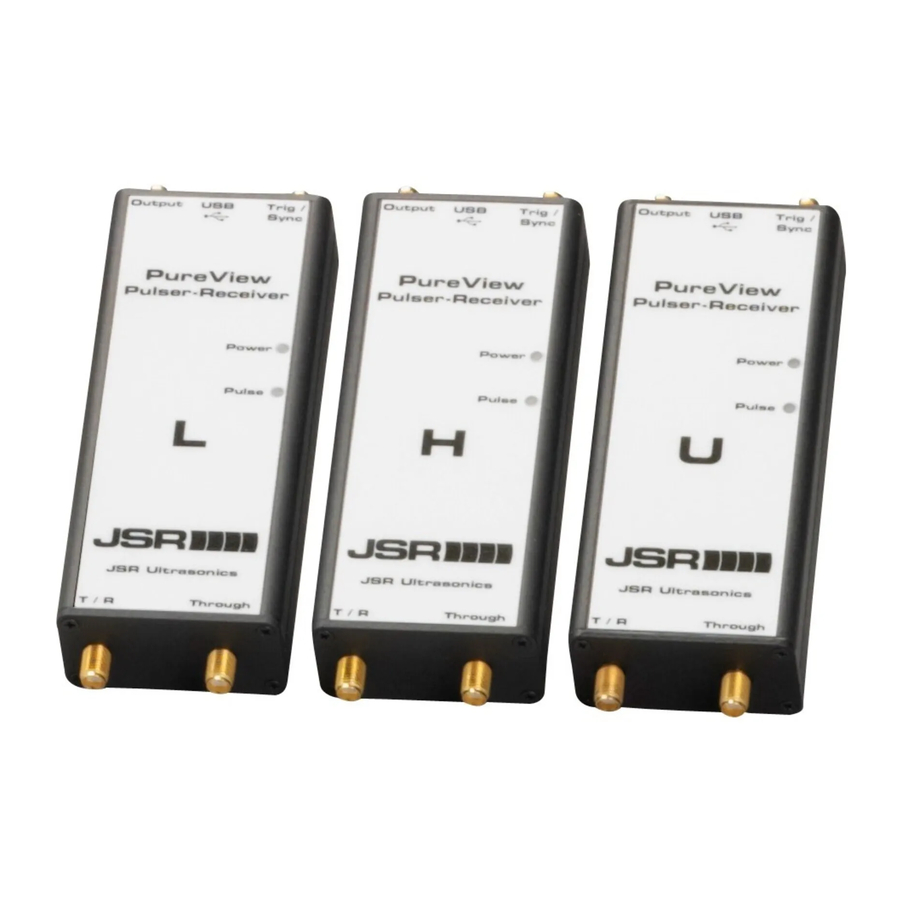
PureView™ Pulser-Receiver Operator Manual PureView Enclosure, Interface Connectors, and Status Indicators PureView Pulser-Receivers have four coaxial SMA connectors, a mini USB connector, and LED status indicators. PureView T/R and Through Connectors As shown in the image below, all PureView models have two coaxial SMA connectors (labeled T/R and Through) for interfacing with one or two ultrasonic transducers. -
Page 13: Pureview Receiver Output, Trig/Sync, And Usb Connectors
PureView™ Pulser-Receiver Operator Manual PureView Receiver Output, Trig/Sync, and USB Connectors PureView employs the three connectors shown in the following image for interfacing with other instrumentation. These three connectors are a Mini-B USB connector for instrument power and control, and two SMA coaxial connectors labeled Output and Trig / Sync. -
Page 14: Pureview Status Indicators
PureView™ Pulser-Receiver Operator Manual Repetition Frequency (PRF) value that is set by control software such as JSR .Net Control Panel. synchronize the PureView operation to other instruments such as an oscilloscope or waveform digitizer, a ~4V positive-polarity Sync pulse is generated on the Trig/Sync connector in synchronization with the transducer-excitation pulse. -
Page 15: System Configuration
After you accept the license terms, the software will be installed automatically. The software can then be launched by clicking the JSR .Net Control Panel icon in the JSR Ultrasonics folder accessed via the Start menu. With JSR .Net Control Panel installed, you can connect the PureView instrument to the PC directly using the supplied USB cable. -
Page 16: Through Mode Configuration
PureView™ Pulser-Receiver Operator Manual connected to the PureView T/R connector. This connection should be made using a short length of high- quality coaxial cable. Pulse-Echo mode operation and configuration is shown in the following figure. Oscilloscope Trig Transducer Figure 2 - Pulse Echo Mode Operation Through Mode Configuration Through operation employs a transmit transducer and a receive transducer. - Page 17 PureView™ Pulser-Receiver Operator Manual The PureView red status indicator ‘Pulse’ LED will illuminate to indicate that the pulser is being triggered. Enable the pulser power supply to produce transducer excitation pulses on the T/R connector. Adjust the frequency of pulser firing such that all echoes from one excitation pulse have subsided before a new excitation pulse is generated.
-
Page 18: Using Jsr .Net Control Panel Software
PureView™ Pulser-Receiver Operator Manual The transducer excitation pulse (typically) occurs 160ns after the rising edge of the Trig / Sync signal. As can be seen in the image above (with a horizontal timescale of 100ns/division), the pulser creates a small disturbance in the receiver output waveform (blue trace) 160ns after the Trig / Sync signal’s rising edge (purple trace). -
Page 19: Receiver Controls In Jsr .Net Control Panel
PureView™ Pulser-Receiver Operator Manual Receiver Controls in JSR .Net Control Panel Power LED User selectable as a constantly-on power indicator or as a blinking indicator (to identify one PureView unit from among multiple units in a multi-unit system). Receiver Mode This control selects the source for the Receiver’s input signal as either Pulse Echo (selects the T/R connector) or Through (selects the Through connector). -
Page 20: Pulser Voltage Supply Enable
PureView™ Pulser-Receiver Operator Manual Pulser Voltage Supply Enable This checkbox in the software enables or disables the power supply voltage that is supplied to the Pulser circuitry. Disabling (unchecking) this control will allow all Pulser-Receiver functions to run but the Pulser will not generate transducer excitation pulses. This control can be useful for debugging PureView-based test systems. -
Page 21: Pureview Instrument Care
PureView™ Pulser-Receiver Operator Manual PureView Instrument Care The PureView encasement is water resistant but not waterproof. Be careful not to immerse the PureView instrument in liquids or to operate it in an environment where it is continuously sprayed by liquids. Should the instrument become wet, carefully dry it. -
Page 22: Appendix A - Pureview Specifications
PureView™ Pulser-Receiver Operator Manual Appendix A - PureView Specifications PureView Power Source: It is highly recommended that all models of PureView Pulser-Receivers be supplied with USB power from an independently-powered USB hub or from a PC’s USB port that offers enhanced-power. A powered hub capable of supplying at least 1A and preferably 2A of current to the PureView instrument is sufficient. - Page 23 PureView™ Pulser-Receiver Operator Manual Miscellaneous Power +5V DC power for PureView™ instrument operation is obtained from a powered USB port. A high-quality low-loss USB cable should be employed to avoid any voltage drop through the cable. Physical Weight 0.152kg (0.33 lbs.) Enclosure Dimensions 124.5mm x 50.3mm x 25.4mm (4.9”...
Need help?
Do you have a question about the PureView Series and is the answer not in the manual?
Questions and answers