
Related Manuals for JSR Ultrasonics DPR300


Summary of Contents for JSR Ultrasonics DPR300
- Page 1 中国代理商-长沙鹏翔电子科技有限公司 DPR300 Pulser/Receiver Operator Manual February, 2011 www.JSRUltrasonics.com Copyright © 2006-2011 Imaginant Inc. All Rights Reserved 0000 0200 1006 D 地址:长沙高新区文轩路27号麓谷企业广场A4栋507 电话: 0731-84668116 传真:0731-84668126...
- Page 2 Computer Requirements ......................15 System Configuration ......................15 Operation..................16 Pulse-Echo Mode Operation ....................16 Transmission Mode Operation....................16 Operating the DPR300 ......................17 Remote Operation of the DPR300 ..........19 Overview of Remote Operation ....................19 JSR Control Panel graphical user interface................20 地址:长沙高新区文轩路27号麓谷企业广场A4栋507 电话: 0731-84668116 传真:0731-84668126...
- Page 3 中国代理商-长沙鹏翔电子科技有限公司 JSR Common SDK (Software Development Kit)..............21 JSR Simple ActiveX object......................22 Remote PC control via serial port commands................22 COM Port Configuration ......................22 PRF Control ..........................23 Pulser....................23 10.1 Receiver ...........................24 10.2 PC or Compatible Control Computer..................24 10.3 Environmental Conditions .......................25 10.4 Miscellaneous ..........................25 地址:长沙高新区文轩路27号麓谷企业广场A4栋507...
-
Page 4: Fuse, Safety, And Technical Support Information
2.2 Technical Support The answers to most questions regarding the use of the DPR300 Pulser/Receiver are contained in this manual. If you cannot find an answer to a question, please contact JSR Ultrasonics technical support at: Imaginant Inc. -
Page 5: Warranty Agreement
中国代理商-长沙鹏翔电子科技有限公司 3 Warranty Agreement 3.1 Instrument Limited Warranty Imaginant Inc. warrants that its instruments will be free from defects in materials and workmanship for a period of one year from the date of purchase. Imaginant will, at its option, repair or replace any of its products that prove to be defective during the warranty period without charge for parts and labor. -
Page 6: General Description
The DPR300 receiver gain is adjustable between -13 dB and 66 dB, and there are six high pass and six low pass filter settings for band-limiting the receiver frequency response. The amplified and filtered signals are available on the instrument’s Receiver Output connector. -
Page 7: Physical
中国代理商-长沙鹏翔电子科技有限公司 4.2 Physical The DPR300 ultrasonic pulser/receiver is a complete instrument on a stand-alone enclosure. The enclosure dimensions are 12” deep, 8.25” wide, and 3.5” high. 地址:长沙高新区文轩路27号麓谷企业广场A4栋507 电话: 0731-84668116 传真:0731-84668126... -
Page 8: Theory Of Operation
5 Theory of Operation 5.1 DPR300 Subsystems and Their Functions The DPR300 pulser/receiver is composed of the functional blocks shown in the figure below. These functional blocks include the front panel and remote control hardware, high voltage power supply, pulser, pulser trigger select, PRF oscillator, receiver amplifier, receiver low pass filters, receiver high pass filters, and the RS-232 interface for instruments with the remote PC control option. - Page 9 Controls the amplification or attenuation of signals processed by the DPR300 receiver. The receiver gain can be varied from -13 dB to +66 dB. The DPR300 receiver has an input impedance of 500 ohms and is available in both 35MHz and 50MHz bandwidths.
- Page 10 These filters are available for eliminating undesirable low frequency energy from the DPR300 receiver signal. High pass filtering can be used as a means of providing faster receiver recovery from strong signals such as the excitation pulse or strong interface echoes.
-
Page 11: Controls, Indicators, And Connectors
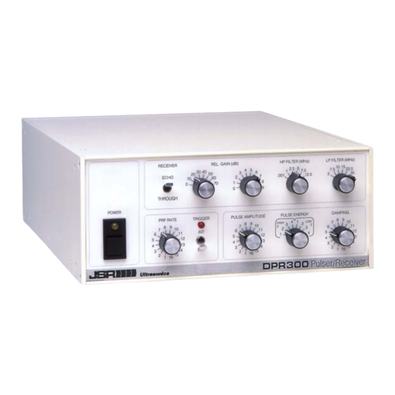
6.1.2 Power Indicator LED (Power) An amber-colored LED that lights to indicate that power is applied to the DPR300. This LED can also be made to blink at a controlled rate by the ‘Blink’ command described in Section 6. 6.1.3 Pulse Indicator LED (Pulse) This is a red LED indicator that illuminates when the DPR300 pulser is firing. - Page 12 中国代理商-长沙鹏翔电子科技有限公司 6.1.4 PRF Control A rotary switch that selects the frequency at which the pulser fires when internal trigger operation is selected. The PRF values range from 100 Hz to 5 kHz. 6.1.5 Int / Ext Switch A toggle switch that selects between internal trigger (PRF) and external trigger sources for the pulser.
- Page 13 6.1.15 Receiver Output Connector (Receiver Output) This connector is a BNC receptacle on which the output signal from the DPR300 receiver is available. This output signal line should be terminated with a 50 Ω load. 6.1.16...
- Page 14 中国代理商-长沙鹏翔电子科技有限公司 If the DPR300 pulser is operated in external trigger mode, then the Trig / Sync connector is used for receiving a positive going 3V to 5 V external trigger pulse. Triggering of the pulser will occur synchronously with the rising edge of the trigger pulse.
-
Page 15: Instrument Setup
DPR300 rear connector labeled RS-232 Input. 4. Plug the power cord into the power receptacle on the rear of the DPR300, and plug the other end into a power outlet of the correct voltage. -
Page 16: Operation
8.2 Transmission Mode Operation For transmission mode operation, separate transmitting and receiving transducers are employed. The transmitting transducer is connected to the DPR300 T/R connector and the receiving transducer is connected to the Through BNC connector. The DPR300 transmission mode configuration is shown in the next figure. -
Page 17: Operating The Dpr300
PC or other computer. Otherwise use the front panel controls to control the instrument. 4. Set the pulse trigger control to INT if the DPR300 pulser is to be triggered by the internal PRF oscillator, and connect the DPR300 Trig/Sync connector to the external trigger input of the monitoring oscilloscope. - Page 18 中国代理商-长沙鹏翔电子科技有限公司 pulse repetition frequency (PRF) should be adjusted such that all echoes from any previous excitation pulses have subsided before a new excitation pulse is generated. 6. Adjust the gain control to obtain a signal level between ± .2 and ± .5 Volts peak into a 50 Ω load at the SIG OUT connector.
-
Page 19: Remote Operation Of The Dpr300
PC. When the PC software first connects to a DPR300, the settings on the front panel controls will be read into the PC software and used without change. -
Page 20: Jsr Control Panel Graphical User Interface
Displays and controls current settings • Query button allows refresh of all values from front panel changes • Controls any number and mix of DPR300, DPR500, or PRC50 instruments • Operates on Windows 2000, Windows XP, Windows Vista, or Windows 7 systems. •... -
Page 21: 中国代理商-长沙鹏翔电子科技有限公司 9.3 Jsr Common Sdk (Software Development Kit)
The JSR Common SDK has an extended property JSR_ID_InstrumentFrontPanelEnables available only on the DPR300. That property allows an application program to disable front panel controls individually. For example, you may wish to have the front panel receiver filters commanded to specific settings but allow the front-panel user to control all other settings. -
Page 22: Jsr Simple Activex Object
PC to an RJ45 receptacle. An RJ45 reversing eight-conductor cable is then used to connect from the serial port to the RS-232 input connector on the DPR300. The pin assignment of the DPR300 rear panel RS-232 interface connectors is shown below. -
Page 23: Prf Control
Maximum Recommended PRF Value vs. Energy Value and Pulser Voltage Value for DPR300 Units with the 900V Pulse Voltage Option When a DPR300 instrument with a 900V pulser option is operated in internal-trigger mode, the above PRF limits will always be applied as the Energy and Voltage values are adjusted. -
Page 24: Receiver
中国代理商-长沙鹏翔电子科技有限公司 1.55 μJoules minimum, 304 μJoules maximum for 475V pulsers. Pulse Energy Dependent upon energy and voltage setting. Typically 10-70 ns FWHM for 50 Ω load. Function of the Energy, Pulse Duration Impedance, and Damping controls. Damping 16 Damping values: 331, 198, 142, 110, 92, 77, 67, 59, 52, 47, 43, 39, 37, 34, 32, and 30 Ohms. -
Page 25: Environmental Conditions
10 W Dimensions 3.9" High, 8.5" Wide, 12.25" Deep Weight 5.0 lbs (2.3 Kg) Operating Temperature 0 to 50 Fuse: .25A 250V 3AG-type slow-blow glass-cartridge fuses Notes: Specifications typical at 25 Imaginant Inc. DPR300 Ultrasonic Pulser/Receiver 地址:长沙高新区文轩路27号麓谷企业广场A4栋507 电话: 0731-84668116 传真:0731-84668126...
Need help?
Do you have a question about the DPR300 and is the answer not in the manual?
Questions and answers