
Subscribe to Our Youtube Channel
Related Manuals for Raymarine Q047


Summary of Contents for Raymarine Q047
- Page 1 Tiller drive autopilot Installation Instructions English Date: 07-2016 Document number: 87279-1-EN © 2016 Raymarine UK Limited...
-
Page 3: Warranty
Raymarine product. To get the best from the product, please read this handbook thoroughly. Warranty To register your new Raymarine product, please take a few minutes to register on the website at www.raymarine.com/warranty Safety notices... -
Page 4: Emc Conformance
Your Raymarine autopilot will add a new dimension to your boating enjoyment. However, it is the skipper’s responsibility to ensure the safety of the boat at all times by following these basic rules: • Ensure that someone is present at the helm AT ALL TIMES, to take manual control in an emergency. -
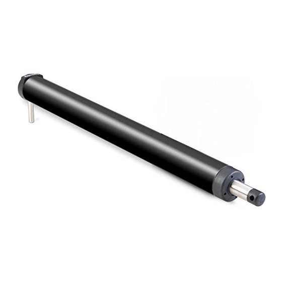
Page 5: Parts Supplied
Parts supplied Plug Cable clip and screw, Tiller drive No 6 x 1/2 in Socket Socket screw No 4 x 3/4 in (x2) Tiller Mounting socket Dimensions 468 mm (18.4 in) 38 mm (1.5 in) midstroke 620 mm (24.5 in) -
Page 6: Critical Dimensions
Critical dimensions Installing the tiller drive involves mounting it between the tiller and a fixed point on the boat’s structure. Two dimensions are critical for correct installation: • Dimension A = 620 mm (24.5 in): the distance from the mounting socket to the tiller pin. Pull out the drive pushrod to this dimension. -
Page 7: Basic Installation
1. Clamp the tiller on the boat’s center line and mark dimensions A and B.Use masking tape to locate the fixing points for the tiller pin and mounting socket. Note: You can measure dimension A on either the port or starboard side of the cockpit, depending on which side you intend to mount the drive. -
Page 8: Installation Accessories
If you need to increase the pushrod length (because of the distance from the mounting socket location to the center line), use a Raymarine pushrod extension. Identifying the correct pushrod extension 1. Clamp the tiller on the boat’s center line. - Page 9 Dimension C Pushrod extension length L Part no. 620 mm (24.5 in) Standard dimension 648 mm (25.5 in) 25 mm (1 in) D003 673 mm (26.5 in) 51 mm (2 in) D004 699 mm (27.5 in) 76 mm (3 in) D005 724 mm (28.5 in) 102 mm (4 in)
- Page 10 Tiller brackets If the tiller is higher or lower than the mounting socket, you can use a Raymarine tiller bracket to vary the tiller pin offset so the drive is horizontal. Identifying the correct tiller bracket 1. Clamp the tiller on the boat’s center line.
- Page 11 D286-2 D287-2...
-
Page 12: Cantilever Mounting
D309-2 Cantilever mounting If you need to attach the tiller drive to a vertical face (such as the cockpit sidewall), use a Raymarine cantilever socket assembly (part number D031): • the maximum possible extension offset is 254 mm (10 in) •... - Page 13 D288-2 Mounting the cantilever assembly To mount the cantilever assembly: 1. Temporarily assemble the cantilever by screwing the rod into the mounting ring. 2. Ensure the drive unit is horizontal and then mark the location of the mounting ring and its mounting holes. 3.
- Page 14 Pedestal socket mounting If you need to raise the height of the drive unit mounting socket to keep the tiller drive horizontal, use a Raymarine pedestal socket assembly. Identifying the correct pedestal socket D289-2 1. Clamp the tiller on the boat’s center line.
- Page 15 Note: When the autopilot is not in use, you can unscrew the complete rod assembly to leave the cockpit unobstructed. Tiller pins Your Raymarine dealer can also supply the following lengths of tiller pin for other non-standard installations. Description Size Part no.
- Page 16 ACU (control unit) connection Rear of socket Terminal identification stripes Drive wire Drive wire (brown). (blue). Insert into Insert into 2-stripe 3-stripe MOTOR POWER terminal terminal Tiller Blue Brown To the D134951 Connect the tiller drive to the control unit via the waterproof plug •...
- Page 17 Installing the socket 1. Apply the template (supplied at the rear of this handbook) to the bulkhead. 2. Carefully drill a 18 mm ( in) clearance hole and two 2.5 mm in) pilot holes. Remove the template. 3. Pass the cable through the bulkhead and attach to the socket, making sure you connect each core to the correct pin, as described in the "ACU (control unit) connection"...
-
Page 18: Specifications
Specifications Drive unit Maximum boat displacement: Wheel drive: 8,500 kg (18,700 lb) Tiller drive: 6,000 kg (13,000 lb) GP Tiller Drive 7,500 kg (16,500 lb) Helm speed: Wheel drive: 9 rpm (designed for systems with 1–3.5 turns lock to lock) Tiller drive: 4.0 sec (lock to lock) Operating conditions:... - Page 20 Tiller drive - plug template Drill 2.5 mm (3/32 inch) Drill 18 mm (23/32 inch) diameter hole (2 positions) diameter hole D5411-1...
- Page 21 User notes...
- Page 22 User notes...
- Page 23 User notes...
- Page 24 www.raymarine.com...
Need help?
Do you have a question about the Q047 and is the answer not in the manual?
Questions and answers