Advertisement
Quick Links
Current Tools
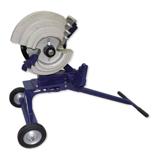
Mechanical Bender
™
MODEL 753
For bending
½" to 1" Rigid/IMC conduit
½" to 1¼" EMT conduit
½" to 1" schedule 40 pipe
Operating, Maintenance, Safety
and Parts Manual
09/2016
Read and understand this material before operating or servicing
this Mechanical Bender. Failure to understand how to safely
operate and service this unit may result in serious injury or death.
This manual is free of charge. All personnel who operate or service this Mechanical Bender should have a
copy of this manual and read and understand its contents. To request a copy, call, write to the address below or
visit our website at www.currenttools.com. All information, specifications and product designs may change
due to design improvements or updates and are subject to change without notice. Current Tools does not
assume any liability for damages resulting from misuse or incorrect application of its products.
CURRENT TOOLS • P. O. BOX 17026 GREENVILLE, SC 29606
800.230.5421 or 864.721.4230 • FAX 864.721.4232
www.currenttools.com
Advertisement

Related Manuals for Current Tools 753

Summary of Contents for Current Tools 753
- Page 1 All information, specifications and product designs may change due to design improvements or updates and are subject to change without notice. Current Tools does not assume any liability for damages resulting from misuse or incorrect application of its products.
-
Page 2: Table Of Contents
TABLE OF CONTENTS Safety Alerts ..................3 Important Safety Information ............4 Specifications ...................5 Operating Instructions ..............5, 6 Stup Up Bending Information ............7 Springback Charts ................8 Offset Bending Information and Charts ........9, 10 Exploded Views and Parts List ............11... -
Page 3: Safety Alerts
SAFETY ALERTS Safety Alert Symbol THIS SAFETY SYMBOL is used to call your attention to instructions that concern your personal safety. It means: ATTENTION! BE AWARE! THIS IS AN IMPORTANT SAFETY INSTRUCTION! Read, understand, and follow these safety instructions. Failure to follow these safety instructions may result in injury or death. -
Page 4: Important Safety Information
RETAIN SAFETY INFORMATION This manual should be read and understood by all personnel who operate or service this Mechanical Bender. Failure to understand how to safely operate and service this unit could result in serious injury or death. This unit should only be operated and serviced by qualified personnel. IMPORTANT SAFETY INFORMATION DANGER DANGER... -
Page 5: Specifications
SPECIFICATIONS – 753 MECHANICAL BENDER Model No. ⁄ Capacity " to 1" RIGID and IMC conduit ⁄ ⁄ " to 1 " EMT conduit ⁄ " to 1" schedule 40 pipe ⁄ ⁄ Overall " × 24 " × 38"... -
Page 6: Operating Instructions
OPERATING INSTRUCTIONS – CONTINUED 6. Adjust the bend degree indicator by hand (see Figure 5a) so that it is at the zero (ø) position when the shoe hook first makes contact with the conduit. 7. Pull the ratchet handle down and return to the up position. Repeat until you have completed the desired bend. -
Page 7: Stup Up Bending Information
STUB-UP BENDING INFORMATION To locate bending marks and springback of 15, 30, 45, 60, and 90 degree bends for a desired stub: 1. Check Springback Chart A, B, or C for deduct length (See page 8). Note that minimum stub length is deduct length plus 2". 2. -
Page 8: Springback Charts
SPRINGBACK CHARTS Chart A – RIGID Conduit/Schedule 40 Pipe ————————— Springback ————————— Conduit Deduct Size Length 15˚ 30˚ 45˚ 60˚ 90˚ 1/2" ⁄ " ⁄ 3/4" " 1" 11" Chart B – EMT Conduit ————————— Springback ————————— Conduit Deduct Size Length 15˚... -
Page 9: Offset Bending Information And Charts
OFFSET BENDING INFORMATION AND CHARTS To locate bending marks for a desired offset: 1. Measure distance from end of conduit to start of bend and mark conduit. (Mark 1) See Figure 9b. 2. Refer to chart E (page 10) for measurement “X" and deduct this distance from Mark 1 and place Mark 2 on conduit. - Page 10 OFFSET BENDING INFORMATION AND CHARTS continued CHART D 15° 30° 45° CENTER CENTER CENTER OFFSET CONDUIT CONDUIT CONDUIT CENTER CENTER CENTER HEIGHT SIZE SIZE SIZE 2" 3/4" 7-3/4" 4" 15-7/16" 3/4" 7-5/16" 1-1/4" 6" 23-3/16" 11-15/16" 1/2" 8-5/16" 1-1/4" 1" 30-7/8"...
-
Page 11: Exploded Views And Parts List
SPRING 751-10 SET SCREW 751-419 SPACER 752-060 SHOE ASSEMBLY 752-068 RATCHET ARM ASSEMBLY 753-001 SCREW – HEX HEAD CAP GR5 ZINC (1/2-13 × 4.5) 753-002 CAP – PLASTIC 753-115 ROLLER SUPPORT WELDMENT 753-116 SHOE MOUNT WELDMENT 747-18 ROLL PIN – 3/16" × 1"...
Need help?
Do you have a question about the 753 and is the answer not in the manual?
Questions and answers