Middle Atlantic C3 Series Instruction Sheet
Display mount option
Hide thumbs
Also See for C3 Series:
- Instruction sheet (13 pages) ,
- Instruction sheet (8 pages) ,
- Instruction sheet (12 pages)
Table of Contents
Advertisement
Quick Links
Instruction Sheet
C3 Series
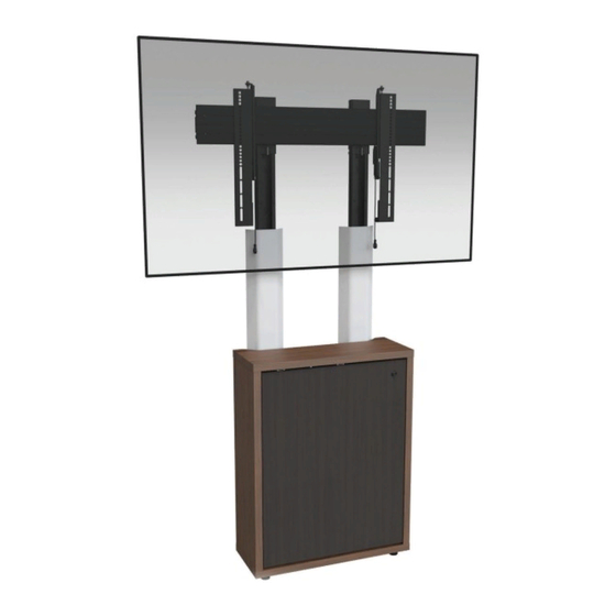
Display Mount Option (C3-XX-LDXU)
NOTE: A 1-Bay C3 credenza with a display mount option (C3-XX-LDXU)
configured for a single displays (display not included) shown.
THANK YOU
Thank you for purchasing a C3 Series Display Mount option. Please read these instructions
thoroughly before installing or assembling this product.
100-00034
Rev A
Advertisement
Table of Contents

Related Manuals for Middle Atlantic C3 Series


Summary of Contents for Middle Atlantic C3 Series
- Page 1 NOTE: A 1-Bay C3 credenza with a display mount option (C3-XX-LDXU) configured for a single displays (display not included) shown. THANK YOU Thank you for purchasing a C3 Series Display Mount option. Please read these instructions thoroughly before installing or assembling this product. 100-00034...
-
Page 2: Important Safety Instructions
It is the responsibility of the Installer/User to ensure that this product is loaded according to specifications. WARNING: Middle Atlantic Products, electrical systems conform to and should be properly grounded in compliance with require- ments of the current National Electrical Code or codes administered by local authorities. All electrical products may present a possible shock or fire hazard if improperly installed or used. -
Page 3: Instructions Importantes Sur La Sécurité
AVERTISSEMENT: Les produits Middle Atlantic, les systèmes électriques sont conformes et doivent être correctement mis à la terre conformément aux exigences du Code national de l'électricité en vigueur ou aux codes administrés par les autorités locales. -
Page 4: Weight Ratings
WEIGHT RATINGS Model Number Weight Rating C3 1-Bay 24” (610 mm) and 32” (813 mm) Height 75 lbs. (34 kg) Per Bay, 25 lbs. (11 kg) On Top, 100 lbs. (45 kg) Maximum Total Rated Load C3 2-Bay 24” (610 mm) and 32” (813 mm) Height 75 lbs. - Page 5 SUPPLIED COMPONENTS AND HARDWARE (CONTINUED) Interface (2x) Standoff Bracket (2x) 5/16”-18 x ½” Flush 5/16”-18 Flange Nut Head Self-Clinching Stud (4x) Model Number Qty. Model Number Qty. (Number of Pairs) Model Number Qty. 5/16” x 3½” C3-24-LD1U C3-24-LD1U Square Single Wire C3-24-LD1U C3-32-LD1U Snap Pin...
-
Page 6: Required Tools
INTRODUCTION NOTE: • Only use this instruction sheet to install your C3 Series Display Mount option after you refer to the C3 Series Credenza Frame instruction sheet (100-00032) and secure your frame to the wall using the default (frame feet) installation height. - Page 7 SETTING MACRO DISPLAY HEIGHT ON YOUR UPRIGHT PAIR (CONTINUED) • There are 4 macro display height intervals labeled A, B, C, and D, along the inner post of each upright. (FIGURE B) • Each macro display height interval is spaced 6” (152 mm) apart. Inner Outer Posts...
- Page 8 ATTACHING UPRIGHT PAIR TO THE FRAME AND YOUR WALL NOTE: • Each upright is attached to specific frame locations based on single or dual display installation. • All models support single display installation. • Only 3- and 4-Bay models support dual display installation. 1.
- Page 9 • For more information, refer to “Attaching Your Frame Using the Default (Frame Feet) Installation Height” on page 6 in the C3 Series Credenza Frame instruction sheet (100-00032). WARNING: All four upper keyholes specified in these instructions are the minimum anchor points required when securing the uprights to the wall.
- Page 10 5. Carefully attach the covers (R) to the front of your uprights. FOR DUAL DISPLAY CONFIGURATIONS ONLY: If you purchased a C3 Series Display Mount Large Cover Option (C3-XX-XCVR-BK) for your dual display configuration, refer to the instruction sheet (100-00035) and use the option instead.
- Page 11 NOTE: This topic must be done as the final part of your C3 installation process. Meaning, if you have not yet installed any other C3 Series options you may have purchased for your credenza, your woodkit, fan kit (if purchased), and large cover option (if purchased), you must first complete those steps (in that order) before returning to this topic and attaching your display(s) (display(s) not included) to the hori- zontal extrusion.
- Page 12 ATTACHING YOUR DISPLAY TO THE HORIZONTAL EXTRUSION (CONTINUED) 3. Use power driver, Phillips bit, (4x) interface pan head screws (IH-A) through (IH-M), spacers (IH-N), and washers (IH-P) to attach the interface pair to the back of your display as shown. (FIGURE M) Location where spacer (IH-N) is used, if necessary.
-
Page 13: Warranty
C3 Series WoodKit instruction sheet (100-00040) to install your woodkit, and then refer to the C3 Series Fan Kit (C3-FANKIT) instruction sheet (100-00039) and/or C3 Series Display Mount Large Cover Option instruction sheet (100-00035) to install your fan kit and/or your large cover option, respectively.
Need help?
Do you have a question about the C3 Series and is the answer not in the manual?
Questions and answers