
Related Manuals for Siemens 38-3AH3-GTD


Summary of Contents for Siemens 38-3AH3-GTD
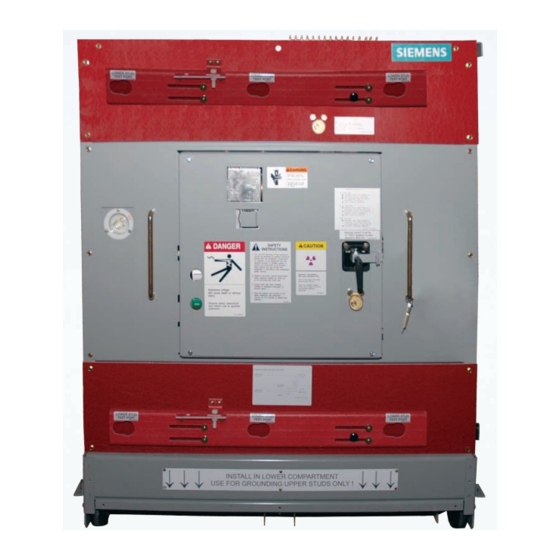
- Page 1 Instruction manual Type 38-3AH3-GTD (B, D, E and F) 38 kV electrically operated ground and test device Installation operation maintenance E50001-F710-A243-V2-4A00 usa.siemens.com/mvswitchgear...
- Page 2 Such persons are permitted maintenance of the equipment purchased. to work within limited approach of exposed Siemens reserves the right to make changes live parts operating at 50 volts or more, and in the specifications shown herein or to...
-
Page 3: Table Of Contents
The sales contract contains the entire obligation of Siemens Industry, Inc. The warranty contained in the contract between the parties is the sole warranty of Siemens Industry, Inc. Any statements contained herein do not create new warranties or modify the existing warranty. -
Page 4: Introduction
(PPE) for the voltage and arc flash incident energy exposure. Introduction The purpose of this instruction manual is The type 38-3AH3-GTD electrically operated to assist the user in developing safe and ground and test device is designed for use efficient procedures for the installation, with Siemens type GM38 metal-clad maintenance and use of the equipment. - Page 5 Field service operation and Signal words warranty issues The signal words “danger,” “warning” and Siemens can provide competent, well- “caution” used in this manual indicate the trained field service representatives to degree of hazard that may be encountered provide technical guidance and advisory by the user.
-
Page 6: Description
38-3AH3-GTD ground and test The "grounding" operation is enabled by device in this instruction manual. selecting the "close" function on the selector... - Page 7 A ground and test device arranged to Elementary diagram allow the upper primary studs to be connected to ground has conductive Table 1: Type 38-3AH3-GTD ground and test device types copper primary extensions in the upper primary disconnect position. These devices are available in two types:...
- Page 8 Test probes current. Depending upon the device type (refer to Table 1: Type 38-3AH3-GTD ground and test Special attention to cleanliness of the cables device types on page 7), a set of three or six and the condition of the insulation is an test probes are provided as a convenient essential requirement for proper use.
- Page 9 Frame interlocks Cable installation for high-voltage Frame interlocks are provided to ensure that test probe ground and test devices may only enter cells 1. Remove the outer retaining ring (refer for which they are intended. Figure 2: Frame to Figure 1: Cable installation in test interlock and closed device interlock probes, item 4b on page 10).
- Page 10 Figure 1: Cable installation in test probes Item Description Space for user’s cable (not shown) Clear tube Bayonet (contact) Retaining ring (4a - inner, 4b - outer) Set screws to secure cable Groove engaged by sliding test port slide...
- Page 11 Figure 2: Frame interlock and closed device interlock location (shown circled) Key transfer interlock Selector switch WARNING DANGER SAFETY CAUTION INSTRUCTIONS ELEMENTARY DIAGRAM USE FOR GROUNDING LOWER STUDS ONLY...
- Page 12 Item Description Masking plate (closed device interlock) Frame-size interlock Circuit breaker operating mechanism Partial side view Partial side view Partial front view Device shown CLOSED Device shown OPEN Device shown OPEN Figure 3: Closed ground and test device blocking interlock Hazardous voltage and high-speed moving parts.
-
Page 13: Operation - Device Types B And D
Operation - device types B and D Figure 4: Type 38-3AH3-GTD ground and test device type B for grounding lower studs ‒ front view Item Description Key transfer interlock (inside channel) (not accessible with device in CONNECT position) Upper test ports... - Page 14 Figure 5: Type 38-3AH3-GTD ground and test device type B for grounding lower studs ‒ side view Item Description Upper test ports Upper test well Lower test ports Lower test well Vacuum interrupter Upper dummy primary Lower conductive primary...
- Page 15 Figure 6: Type 38-3AH3-GTD ground and test device type D for grounding upper studs ‒ front view Item Description Key transfer interlock (inside channel) (not accessible with device in CONNECT position) Upper test ports and test port slide Selector WARNING...
- Page 16 Figure 7: Type 38-3AH3-GTD ground and test device type D for grounding upper studs ‒ side view Item Description Upper test ports Upper test well Lower test ports Lower test well Vacuum interrupter Upper dummy primary Lower conductive primary...
- Page 17 Figure 8: Elementary diagram for device arranged to ground lower Upper stud studs type B test port Upper stud (dummy) Grounding switch Lower stud Lower stud test port (conductive) Ground Figure 9: Elementary diagram for device arranged to ground upper Upper stud studs type D test port...
- Page 18 Selector switch Key interlock description Test port interlock: Off position: Locks test port closed in preparation Control power disconnected for a grounding operation Padlockable in this position Key works in the key transfer interlock. l Key required from key transfer For device types B and D, the test port key interlock to operate interlock must be operated as the first step...
- Page 19 Hazardous voltage and high currents. Can cause death, serious injury and property damage. Extend the control cable to its full length. Use the CLOSE-OPEN pushbutton control station as far from the switch- gear compartment to be grounded as possible and off to the side rather than in the front.
- Page 20 GTD ground and test device types direction. Reference to Table 1: on page 7 and the discussion of Type 38-3AH3-GTD ground and device types earlier in this test device types on page 7, instruction manual.
- Page 21 The test port key interlock shall have its A1.5.2 Insert the key in the key transfer key inserted and bolt withdrawn. interlock, but do not turn it. Try to remove the second key in the key One key will be present and held in the transfer interlock.
- Page 22 A1.5.8 Refer to the ground and test device The ground and test device rating plate located on the front of then automatically closes, the device, and determine the opening the 52b contacts correct control voltage. Control driven by the major bell crank power may be applied by use of the of the device.
- Page 23 A2. System test procedures Note: Rules of identification in section A1 It is imperative that the user become totally and refer to Table 1: Type 38-3AH3-GTD familiar with every aspect of a ground and ground and test device types on page 7 as well as Figure 4: Type 38-3AH3-GTD test device before using it.
- Page 24 Close and latch the door of the Close and latch the door of the circuit breaker cell and rack the circuit breaker cell and rack the type 38-3AH3-GTD ground and test type 38-3AH3-GTD ground and test device to disconnected position device to connected position using...
- Page 25 Procedure for grounding. It is Note: Rules of identification in section A1 imperative that the user become and refer to Table 1: Type 38-3AH3-GTD totally familiar with every aspect of ground and test device types on page 7 as a ground and test device before well as Figure 4: Type 38-3AH3-GTD ground using it.
- Page 26 Close and latch the door of the which is to be grounded. circuit breaker cell and rack the A2.2.8 Attach (plug in) the CLOSE-OPEN type 38-3AH3-GTD ground and test pushbutton station and control device to connected position using cable. the same procedures as for racking the type 38-3AH3 38 kV circuit A2.2.9...
- Page 27 Hazardous voltage and high currents. Can cause death, serious injury and property damage. Extend the control cable to its full length. Use the CLOSE-OPEN pushbutton control station as far from the switchgear compartment to be grounded as possible and off to the side rather than in the front.
- Page 28 Make no assumptions, and Close and latch the door of the double check each step! circuit breaker cell and rack the type 38-3AH3-GTD ground and test A2.3.1 Complete operational checkout of device to disconnected position the ground and test device and...
- Page 29 A236-X-XXXX for type GM38 Note: Rules of identification in section A1 switchgear. and refer to Table 1: Type 38-3AH3-GTD ground and test device types on page 7 Close and latch the door of the as well as Figure 4: Type 38-3AH3-GTD...
- Page 30 Close and latch the door of the padlock, as appropriate) the test circuit breaker cell and rack the port slide, and move the test port type 38-3AH3-GTD ground and test slide aside to expose test ports device to disconnected position for the upper or lower studs, using the same procedures as for whichever are to be tested.
-
Page 31: Operation - Device Types E And F
Operation - device types E and F Figure 10: Type 38-3AH3-GTD ground and test device type E for grounding lower studs ‒ front view Item Description Remote control cable receptacle Selector switch and key interlock with padlock provision Selector Padlock... - Page 32 Figure 11: Type 38-3AH3-GTD ground and test device type E for grounding lower studs ‒ side view Item Description Lower test ports Lower test well Vacuum interrupter Lower conductive primary...
- Page 33 Figure 12: Type 38-3AH3-GTD ground and test device type F for grounding upper studs ‒ front view Item Description Upper test ports and test port slide Remote control cable receptacle Padlock provision Test port ELEMENTARY Selector DIAGRAM WARNING switch Selector switch...
- Page 34 Figure 13: Type 38-3AH3-GTD ground and test device type F for grounding upper studs ‒ side view Item Description Upper test ports Upper test well Vacuum interrupter Upper conductive primary...
- Page 35 Figure 14: Elementary diagram for device arranged to ground lower studs type E Grounding switch Lower stud Lower stud (conductive) test port Ground Figure 15: Elementary diagram for device arranged to ground upper studs type F Upper stud Upper stud (conductive) test port Grounding...
- Page 36 Selector switch Selector switch The selector switch allows selection of Off position: CLOSE, OFF or TRIP (open) functions. Control power disconnected Mechanically, it blocks the ground and test Padlockable in this position device trip latch in the CLOSE and OFF positions.
- Page 37 Reference to Table 1: instruction manual. Type 38-3AH3-GTD ground and test device types on page 7, Figures B1.3 Interlock function. A key interlock is 10-13 and the ground and test...
- Page 38 B1.4 Electrical operation check B1.4.5 Refer to the ground and test device Refer to typical schematic diagram rating plate located on the front of illustrated in Figure 16: Typical the device, and determine the ground and test device schematic correct control voltage. Control on page 47 for all discussions power may be applied by use of the related to wiring or control circuits.
- Page 39 The ground and test device B1.4.10 The sequence allowed by the then automatically closes, control circuit is as follows: opening the 52b contacts Selector switch is in the TRIP driven by the major bell position: crank of the device. The 52b contact 41-42 opens Switch contacts TS/T 12-13 the spring release coil...
- Page 40 B2.1 Live terminal detection, line-to-line Note: Rules of identification in section B1 and line-to-ground measurements. and refer to Table 1: Type 38-3AH3-GTD ground and test device types on page 7 B2.1.1 Complete operational checkout of as well as Figure 10: Type 38-3AH3-GTD...
- Page 41 Close and latch the door of the Release the latches and open the circuit breaker cell and rack the cell door, and remove the type type 38-3AH3-GTD ground and test 38-3AH3-GTD ground and test device to connected position using device from the circuit breaker cell...
- Page 42 E50001-F710- Note: Rules of identification in section B1 A236-X-XXXX for type GM38 and refer to Table 1: Type 38-3AH3-GTD switchgear. ground and test device types on page 7 Close and latch the door of the...
- Page 43 Important: If the voltage measurements B2.2.10 Extend the control cable to its full indicate that the studs to be grounded length, so that the CLOSE-OPEN are energized, do not proceed with pushbutton control station is as far grounding these disconnects. from the switchgear compartment to be grounded as possible, and off Severe electrical distribution...
- Page 44 GM38 switchgear. compartment. Close and latch the door of the circuit breaker cell and rack the type 38-3AH3-GTD ground and test device to disconnected position using the same procedures as for racking the type 38-3AH3 38 kV circuit breaker.
- Page 45 Note: Rules of identification in section B1 B2.3 The procedure for dielectric testing and refer to Table 1: Type 38-3AH3-GTD (or insulation resistance testing) of ground and test device types on page 7 primary circuits. It is imperative...
- Page 46 Close and latch the door of the equipment. circuit breaker cell and rack the type 38-3AH3-GTD ground and test A2.3.7 After completing the dielectric or device to connected position using insulation resistance testing...
-
Page 47: Schematic
Schematic Figure 16: Typical ground and test device schematic Legend: Pushbutton enclosure 88 - Spring charging motor 52SRC - Spring release coil (close) 4/C cable 52T - Shunt trip coil (trip) Green White Black Receptacle plug 52Y - Closing relay (anti-pump) Ground and test device mounted receptacle LS5 5A LS3 - Spring-charge switch (open when... - Page 48 Actual results are dependent on variable conditions. Accordingly, Siemens does not make representations, warranties, or assurances as to the accuracy, currency or completeness of the content contained herein.
Need help?
Do you have a question about the 38-3AH3-GTD and is the answer not in the manual?
Questions and answers