
Subscribe to Our Youtube Channel
Related Manuals for Accorroni HPE R32 INVERTER Series


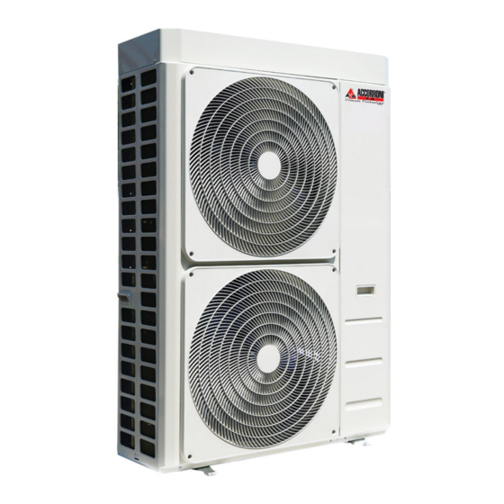
Summary of Contents for Accorroni HPE R32 INVERTER Series
- Page 1 Air / water inverter heat pumps with axial fans for Hot / Cold and DHW production HPE R32 04÷18T INVERTER...
-
Page 2: Table Of Contents
CONTENTS PURPOSE AND CONTENTS OF THE MANUAL ......................5 HOW TO KEEP THE MANUAL ............................5 GRAPHIC SYMBOLS USED IN THE MANUAL ........................ 5 NORMATIVE REFERENCES ............................... 5 PERMITTED USE ................................... 6 GENERAL SAFETY GUIDELINES ............................6 WORKERS’ HEALTH AND SAFETY ..........................6 PERSONAL PROTECTIVE EQUIPMENT ........................... - Page 3 DECOMMISSIONING ................................29 10.1 ..................................30 ESIDUAL RISKS TECHNICAL DATA ................................37 11.1 TECHNICAL SHEET ................................37 11.2 UNIT AND AUXILIARY ELECTRICAL DATA ....................... 41 OPERATING LIMITS ................................42 12.1 EVAPORATOR WATER FLOW RATE ..........................42 12.2 COLD WATER PRODUCTION (SUMMER MODE) ......................42 12.3 HOT WATER PRODUCTION (WINTER MODE) ......................
-
Page 4: Purpose And Contents Of The Manual
The manual of the HPE R32 units contains all the necessary information for optimal use of the equipment under safe conditions for the operator. 1 PURPOSE AND CONTENTS OF THE MANUAL This manual provides basic information as to the selection, installation, operation and maintenance of the HPE R32 unit. It is intended for the operators of the appliance and it enables them to use the equipment efficiently, even if they do not have any previous specific knowledge. -
Page 5: Permitted Use
EN 14511-1:2018. EN 14511-2:2018. EN 14511-3:2018. EN 14511-4:2018 • • EN 14825:2018 3 PERMITTED USE • The company excludes any contractual and extra contractual liability for damage caused to persons, animals or objects, by incorrect installation, setting and maintenance, improper use of the equipment, and the partial or superficial reading of the information contained in this manual. -
Page 6: Personal Protective Equipment
The unit works with R32 refrigerant, which is included in the list of greenhouse gases (GWP 675) which are subject to the requirements in EU regulation n. 517/2014 called “F-GAS” (mandatory in the European zone). Among the provisions of this regulation, it sets forth that operators working on systems running with greenhouse gases be in possession of a certification, issued or acknowledged by the competent authorities, attesting that they have passed a test authorising them to perform this work. -
Page 7: Refrigerant Safety Data Sheet
REFRIGERANT SAFETY DATA SHEET Name: R32. HAZARDS IDENTIFICATION Main hazards: Asphyxiation. Specific hazards: Quick evaporation could cause it to freeze. FIRST AID MEASURES General information: Do not administer to people who are unconscious. Inhalation: Immediately remove to fresh air. Use oxygen or artificial respiration as required. The use of adrenaline or similar drugs should be avoided. -
Page 8: Specific R32 Gas Warnings
Stability: Stable under normal conditions. Materials to avoid: Air, oxidizing agents, humidity. Under normal storage and use conditions, hazardous decomposition products should not be Decomposition products generated. hazardous: TOXICOLOGICAL INFORMATION Acute toxicity: LD/LC50/inhalation/4 hours/on rat >1107000 mg/m Local effects: No known effect. Long-term toxicity: No known effect. -
Page 9: General
GENERAL When installing or intervening on the chiller unit, it is necessary to strictly follow the rules listed in this manual, to observe all the indications on the unit and however to take all possible precautions. Failure to comply with the rules reported on this manual can create dangerous situations. -
Page 10: Positioning And Minimum Technical Clearances
POSITIONING AND MINIMUM TECHNICAL CLEARANCES All models of the HPE R32 range are designed and constructed for outdoor installations. It is advisable to create an adequately sized support base for the unit. The units transmit a small amount of vibrations to the ground: it is nonetheless advisable to apply vibration dampers between the base frame and support surface. - Page 11 Do not obstruct or cover the vents on the top cover. In the event of side-by-side units, the minimum Lmin distance between them is 1 m. Covering with canopies or placing near plants or walls should be avoided to prevent air recirculation. In the event of winds stronger than 2.2 m/s the use of wind barriers is recommended.
-
Page 12: Dimensions
DIMENSIONS 5.4.1 Model HPE R32 06 / 08 IN/OUT: 1”M G E: power supply input... -
Page 13: Model Hpe R32 10 / 10T / 12 / 12T
5.4.2 Model HPE R32 10 / 10T / 12 / 12T IN/OUT: 1”M G E: power supply input 5.4.3 Model HPE R32 14/14T/16/16T/18T IN/OUT: 1”M G E: power supply input... -
Page 14: Accessing The Inner Parts
ACCESSING THE INNER PARTS 5.5.1 Mod. HPE R32 06 / 08 DETAIL A SCALE 1 : 3 DETAIL B SCALE 1 : 4 Interlocking tab 1) Remove the cover 2) Undo the screws (number 2; 3; 4) of the sheet metal cover of the user interface and the screw (number 1) of the side panel to separate the front sheet metal from the side panel (Detail A). -
Page 15: Mod. Hpe R32 14 / 16
5.5.3 Mod. HPE R32 14 / 16 DETAIL A SCALE 1 : 1 DETAIL B SCALE 1 : 2 1) Remove the cover by undoing the screws (number 1; 2; 3; 4; 5; 6; 7; 8;9). 2) Undo the screws (number 10; 11) of the front sheet and then push the panel downwards to remove the tabs (Detail A); pull the panel forward to remove it. -
Page 16: Features Of The Circuit Water
5.6.1 Features of the circuit water To guarantee correct operation of the unit, the water must be appropriately filtered (see the instructions at the start of this paragraph) and there must be only a minimum amount of dissolved substances. The maximum allowed values are shown below MAXIMUM CHEMICAL-PHYSICAL PROPERTIES ALLOWED FOR THE CIRCUIT WATER 7.5 - 9 Electrical conductivity... -
Page 17: Filling The System
Each unit is therefore fitted with a hole on the base of the hydronic kit (on the coil side) to drain condensation which could drip from the pipes of the plumbing system. Since these pipes are well insulated, a minimum amount of condensation is produced anyway and therefore it is not mandatory to connect a drain pipe to this fitting. -
Page 18: Functional Diagrams
FUNCTIONAL DIAGRAMS 5.7.1 HPE R32 04/06 / 08 CODE NUM. DESCRIPTION CODE NUM. DESCRIPTION COMPRESSOR H/CS UTILITY WATER OUTLET CO/EV CONDENSER (IN CHILLER MODE) H/CR UTILITY WATER INLET EV/CO EVAPORATOR (IN CHILLER MODE) PEHTC HIGH PRESSURE TRANSDUCER ELECTRONIC EXPANSION VALVE PEDTR LOW PRESSURE TRANSDUCER YISV... -
Page 19: Hpe R32 10 / 10T / 12 / 12T
5.7.2 HPE R32 10 / 10T / 12 / 12T CODE NUM. DESCRIPTION CODE NUM. DESCRIPTION COMPRESSOR H/CS UTILITY WATER OUTLET CO/EV CONDENSER (IN CHILLER MODE) H/CR UTILITY WATER INLET EV/CO EVAPORATOR (IN CHILLER MODE) PEHTC HIGH PRESSURE TRANSDUCER ELECTRONIC EXPANSION VALVE PEDTR LOW PRESSURE TRANSDUCER YISV... -
Page 20: Hpe R32 14/14T / 16 / 16T / 18T
5.7.3 HPE R32 14/14T / 16 / 16T / 18T CODE NUM. DESCRIPTION CODE NUM. DESCRIPTION COMPRESSOR H/CS UTILITY WATER OUTLET CO/EV CONDENSER (IN CHILLER MODE) H/CR UTILITY WATER INLET EV/CO EVAPORATOR (IN CHILLER MODE) PEHTC HIGH PRESSURE TRANSDUCER ELECTRONIC EXPANSION VALVE PEDTR LOW PRESSURE TRANSDUCER YISV... -
Page 21: Electrical Connections
ELECTRICAL CONNECTIONS Check that the power supply matches the unit’s electric nominal data (voltage, phases, frequency) displayed on the rating plate on the unit’s side panel. The electric power connections must be made in accordance to the wiring diagram enclosed with the unit and in conformity with national and international standards (providing general circuit breaker, residual current devices for each line, proper earthing of the plant, etc.). - Page 22 The power cables, electrical protections and line fuses must be sized in accordance with what is reported in the unit's wiring diagram and in the electrical data contained in the technical characteristics table (see Paragraph 11). Use a dedicated power line, do not power the appliance through a line to which other users are connected. Fasten the power cables securely and make sure they do not come into contact with sharp corners.
-
Page 23: User Terminal Block
5.8.3 User terminal block The connection terminal block is located under the machine cover. For access, see the instructions in paragraph 5.8.1. The terminal block must be connected respecting the notes below. The connections shown below are standard. Other connections are given in the MCO manual of the on-machine control of the i- 32V5 (see "USER AND INSTALLER CONFIGURATION TABLES"), according to the configurations adopted. - Page 24 Terminal board HPE R32 04/06/08/10/12/14/16 (1ph) Terminal board HPE R32 10T/12T/14T/16T/18T (3ph) XGI-9.2 XGI-8.2 XGI-7.2 XGI-6.2 XGI-5.2 XGI-4.2 XGI-3.2 XGI-2.2 XGI-1.2 XGI-8.1 XGI-9.1 XGI-7.1 XGI-5.1 XGI-4.1 XGI-3.1 XGI-2.1 XGI-1.1 TERMINAL BOARD Gi...
-
Page 25: Control Logics
5.8.4 Control logics For the control logics, see the manual cod. MCO01110L8500. 5.8.5 Fuses Details on the type and nominal specifications of the fuses are set out on the machine’s data plate, on electrical schemes as well as on the fuses. 6 STARTUP Before start-up: •... -
Page 26: Shutdowns For Long Periods
8 SHUTDOWNS FOR LONG PERIODS The shutdown mode of the plant depends on the site of application and the time the plant is expected to be shut down. If the unit is equipped with the antifreeze system, even when off (system on unit at “off” position), the antifreeze system keeps running if power supply continuity to the equipment is guaranteed. -
Page 27: Cleaning The Finned Coil
Check that the electric terminals both inside the electric panel and in the terminal blocks of the compressor are well tightened. Tightening of plumbing connections. Check fixing and balancing of the fans. Correct electrical voltage and phase imbalance (without load and under load). Correct absorption. -
Page 28: Decommissioning
abide by the obligations indicated above. Special attention is therefore recommended during maintenance so as to reduce refrigerant leaks as far as possible. 10 DECOMMISSIONING Once the unit has reached the end of its life cycle and needs to be replaced, the following operations are recommended: •... -
Page 29: Residual Risks
10.1 Residual risks This paragraph sets forth any residual risks which cannot be eliminated by the manufacturer in the design stage. Risk due to: Precautions/Corrections There is always the risk of the unit falling or tipping over during handling. Follow the instructions in the Handling “Handling”... - Page 30 Sources of ignition When carrying out work on a refrigerant circuit that contains or ■ previously contained flammable refrigerant, never use sources of ignition that could ignite the refrigerant. Remove all possible sources of ignition, including cigarettes, from the area where installation, repair, dismantling or disposal work is taking place that may result in refrigerant escaping.
- Page 31 Measure Completed Notes Checking the refrigeration system Any replacement electrical components must be suitable for the ■ application and must correspond to the manufacturer’s specifi- cation. Only replace faulty components with genuine spare parts. Carry out all component replacements in accordance with ■...
- Page 32 Measure Completed Notes Repairs on sealed enclosures When carrying out work on sealed components, fully isolate the ■ appliance from the power supply, also before removing sealed covers. If a power supply is absolutely necessary during the work: Posi- ■ tion a continuously operating refrigerant detector in the most critical locations, to provide warning of any potentially danger- ous situation.
- Page 33 Measure Completed Notes Leak detection The following leak detection processes are suitable for systems with flammable refrigerants: Leak detection with electronic refrigerant detectors: Electronic refrigerant detectors may not have the required sensi- ■ tivity or may need to be calibrated to the relevant range. Carry out the calibration in refrigerant-free surroundings.
- Page 34 them. – Cylinders shall be kept upright. – Ensure that the refrigeration system is earthed prior to charging the system with refrigerant. – Label the system when charging is complete (if not already). – Extreme care shall be taken not to overfill the refrigeration system.
- Page 35 that the correct number of cylinders for holding the total system charge are available. All cylinders to be used are designated for the recovered refrigerant and labelled for that refrigerant (i.e. special cylinders for the recovery of refrigerant). Cylinders shall be complete with pressure relief valve and associated shut-off valves in good working order.
-
Page 36: Technical Data
11 TECHNICAL DATA 11.1 TECHNICAL SHEET HPE R32 TECHNICAL SPECIFICATIONS Unit of measurement Cooling capacity (1) 3,03 / 4,23 / 3,20 / 5,02 / 3,80 / 6,08 / 4,66 / 7,53 / 4,65* 5,52* 6,69* 8,28* min/nom/max Input power (1) 1,29 1,60 1,99... - Page 37 Internal heat exchanger type Plates Internal heat exchanger No. internal heat exchangers Water content Water content of hydronic circuit Maximum water side pressure Plumbing fittings inch 1"M 1"M 1"M 1"M Minimum water volume Water circuit Nominal circulator output 0,075 0,075 0,075 0,075 Maximum circulator output...
- Page 38 SCOP (6) 4,53 4,47 4,47 4,48 Water flow rate (4) 0,47 0,55 0,55 0,65 User side heat exchanger pressure drops 13,1 13,1 13,0 Nominal useful head (4) 55,2 43,4 43,4 63,6 Energy efficiency Classe A+++/A++ A+++/A++ A+++/A++ A+++/A++ water 35°C / 55°C Twin Rotary Twin Rotary Twin Rotary...
- Page 39 HPE R32 Unit of TECHNICAL SPECIFICATIONS measurement Cooling capacity (1) 6,87 / 11,48 5,99 / 13,80 / 5,99 / 13,80 6,86 15,04 / / 12,05* 14,49* / 14,49* 15,79* min/nom/max Input power (1) 3,53 4,38 4,38 4,88 E.E.R. (1) 3,25 3,15 3,15 3,08...
-
Page 40: Unit And Auxiliary Electrical Data
Water content of hydronic circuit Maximum water side pressure Plumbing fittings inch 1"M 1"M 1"M 1"M Minimum water volume Water circuit Nominal circulator output 0,14 0,14 0,14 0,14 Maximum circulator output 0,14 0,14 0,14 0,14 Max circulator absorbed current 1,10 1,10 1,10 1,10... -
Page 41: Operating Limits
12 OPERATING LIMITS 12.1 EVAPORATOR WATER FLOW RATE The nominal water flow rate refers to a 5°C temperature difference between the evaporator inlet and outlet. The maximum permitted flow rate features a 3°C temperature difference while the minimum one has an 8°C temperature difference at the nominal conditions as shown in the technical sheet. - Page 42 HEAT PUMP MODE Heating CHILLER MODE Cooling...
- Page 43 DOMESTIC HOT WATER MODE DHW mode...
-
Page 44: User Interface - Controller
13 USER INTERFACE - CONTROLLER The unit includes a display placed underneath a hinged polycarbonate transparent door with a protection rating of IP67. The interface has a part with variable text and a series of icons identifying operation of the unit as shown in the table below. •... -
Page 45: Menu
13.1 MENU The following are the main features for navigating the menus, especially describing functions which are not obvious. The main menu has the following items: MENU LABEL PASSWORD LEVEL OTHER CONDITIONS Setpoint User Not accessible if connected to Hi-t2 Probes Installer Alarms... - Page 46 A2B Accorroni E.G. s.r.l. Via d’Ancona, 37 - 60027 Osimo (An) - Tel. 071.723991 web site: www.accorroni.it - e-mail: a2b@accorroni.it...
Need help?
Do you have a question about the HPE R32 INVERTER Series and is the answer not in the manual?
Questions and answers