Table of Contents
Advertisement
Advertisement
Table of Contents

Subscribe to Our Youtube Channel
Related Manuals for Klein Tools MM400


Summary of Contents for Klein Tools MM400
- Page 1 MM400 ENGLISH INSTRUCTION MANUAL Auto-Ranging Digital Multimeter Digital Multimeter • DATA HOLD • AUDIBLE CONTINUITY • MIN / MAX • TEMPERATURE • DIODE TEST • CAPACITANCE 600V GlobalTestSupply www. .com Find Quality Products Online at: sales@GlobalTestSupply.com...
-
Page 2: General Specifications
ENGLISH GENERAL SPECIFICATIONS Klein Tools MM400 is an auto-ranging multimeter that measures AC/DC voltage, AC/DC current, and resistance. It can also measure temperature, capacitance, frequency, duty-cycle, and test diodes and continuity. • Operating Altitude: 6562 ft. (2000m) • Relative Humidity: <80% non-condensing •... -
Page 3: Electrical Specifications
ELECTRICAL SPECIFICATIONS VOLTAGE (AUTO-RANGING) Function Range Resolution Accuracy 4.000V ±(1.2% + 5 digits) 40.00V 10mV AC Voltage ±(1.5% + 5 digits) (V AC) 400.0V 100mV 600V ±(2.0% + 5 digits) 400.0mV 0.1mV ±(1.0% + 8 digits) 4.000V DC Voltage 40.00V 10mV ±(1.2% + 3 digits) (V DC) -
Page 4: Duty Cycle
ENGLISH ELECTRICAL SPECIFICATIONS CAPACITANCE (AUTO-RANGING) Range Resolution Accuracy 40.00nF 10pF ±(5.0% + 35 digits) 400.0nF 0.1nF 4.000 F ±(3.0% + 5 digits) 40.00 F 10nF 200.0 F 0.1 F ±(5.0% + 5 digits) Maximum Input: 600V DC or 600V AC RMS FREQUENCY (AUTO-RANGING) 9.999Hz 0.001Hz... - Page 5 ELECTRICAL SPECIFICATIONS • Diode Test: 1.5 mA max, open circuit voltage 3.0V DC • Continuity Check: Audible signal <50Ω • Sampling Frequency: 3 samples per second • Overload: "OL" indicated on display, overload protection 600V RMS in all settings • Polarity: "-" on display indicates negative polarity •...
-
Page 6: Symbols On Meter
ENGLISH SYMBOLS ON METER AC/DC Voltage or Current Resistance (in Ohms) Audible Continuity Diode Capacitance Frequency Duty-cycle Double Insulated Class II °F/°C Temperature (Fahrenheit / Celsius) Ground Fuse (with rating below symbol) Warning or Caution To ensure safe operation and service of this meter, follow all warnings and instructions detailed in this manual. -
Page 7: Feature Details
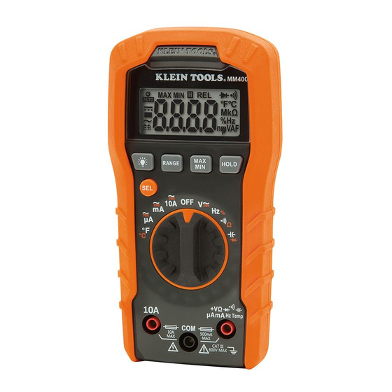
FEATURE DETAILS NOTE: There are no user-serviceable parts inside meter. 4000 count LCD display Backlight ON/OFF button Function selector switch "RANGE" button "10A" jack "MAX/MIN" button "COM" jack "HOLD" (Data Hold) button "V " jack "SEL" (Select) button GlobalTestSupply www. .com Find Quality Products Online at: sales@GlobalTestSupply.com... -
Page 8: Function Buttons
ENGLISH FUNCTION BUTTONS ON/OFF To Power ON the meter rotate the Function Selector switch from the OFF setting to any measurement setting. To Power OFF the meter rotate the Function Selector switch to the OFF setting. By default, the meter will automatically Power OFF after 30 minutes of inactivity. - Page 9 OPERATING INSTRUCTIONS CONNECTING TEST LEADS Do not test if leads are improperly seated. Results could cause intermittent display readings. To ensure proper connection, firmly press leads into the input jack completely. INCORRECT CORRECT TESTING IN CAT III / CAT IV MEASUREMENT LOCATIONS Ensure the test lead shield is pressed firmly in place.
- Page 10 ENGLISH OPERATING INSTRUCTIONS AC/DC VOLTAGE (LESS THAN 600V) 1. Insert RED test lead into V jack , and BLACK test lead into COM jack , and rotate function selector switch the V setting. NOTE: The meter defaults to AC measurement. Press the "SEL" button to toggle between AC and DC modes.
- Page 11 OPERATING INSTRUCTIONS AC/DC CURRENT NOTE: The meter defaults to AC measurement. Press the "SEL" button to toggle between AC and DC modes. The AC or DC icon on the LCD indicates which mode is selected. 1. Attach test leads to the appropriate jacks and rotate function selector switch to the appropriate setting as follows: •...
-
Page 12: Resistance Measurements
ENGLISH OPERATING INSTRUCTIONS 2. To measure current: Remove power from circuit, open circuit at measurement point, connect meter in-series in the circuit using the test leads, and apply power to circuit. 3. Measure the current. The meter will auto-range to display the measurement in the most appropriate range. - Page 13 OPERATING INSTRUCTIONS CONTINUITY 1. Insert RED test lead into V jack , and BLACK test lead into COM jack , and rotate function selector switch to the Continuity/Resistance setting. NOTE: The meter defaults to Continuity testing in this mode. Ensure that the Continuity Testing icon is visible on the display.
-
Page 14: Diode Test
ENGLISH OPERATING INSTRUCTIONS CAPACITANCE 1. Insert RED test lead into V jack , and BLACK test lead into COM jack , and rotate function selector switch to the Capacitance/Diode setting. NOTE: The meter defaults to Capacitance testing in this mode. Ensure that the display reads "0 nF"... -
Page 15: Frequency / Duty-Cycle
OPERATING INSTRUCTIONS FREQUENCY / DUTY-CYCLE 1. Insert RED test lead into V jack and BLACK test lead into COM jack , and rotate function selector switch to the Frequency/Duty-Cycle setting. NOTE: The meter defaults to Frequency testing in this mode. To enter Duty-Cycle testing mode, press the "SEL"... -
Page 16: Maintenance
ENGLISH MAINTENANCE BATTERY REPLACEMENT When indicator is displayed on LCD, batteries must be replaced. 1. Remove screw from battery door. 2. Replace 2 x AAA batteries (note proper polarity). 3. Replace battery door and fasten securely with screw. To avoid risk of electric shock, disconnect leads from any voltage source... - Page 17 CLEANING Be sure meter is turned off and wipe with a clean, dry lint-free cloth. Do not use abrasive cleaners or solvents. STORAGE Remove the batteries when meter is not in use for a prolonged period of time. Do not expose to high temperatures or humidity.
Need help?
Do you have a question about the MM400 and is the answer not in the manual?
Questions and answers