Advertisement
Quick Links
Mounting Instructions
1 General
These mounting instructions are the basis for the approval by ECBS, VdS, A2P (CNPP), DNV or UL. Installation of the
lock exclusively in accordance with these instructions.
Guidelines of the national certification bodies are to be considered and complied with in addition.
Use high quality alkaline/manganese monobloc batteries only. Low quality batteries may cause oxidation which results in a
functional failure of the lock.
Avoid residual crystalline moisture in the cabinet (e.g. from varnishing) so as to prevent attack of the electrical contacts.
Make sure that ingress of dirt or detergents (e.g. remaining fillers or cold cleaners) is prevented.
Do not grease/oil the lock or key.
2 Mounting instructions for lock and control unit
RH version (standard version):
-
Bolt left, keyhole horizontal
Lock downwards, keyhole vertical
Lock upwards, keyhole vertical
LH version
-
Bolt right, keyhole horizontal
Stand 15.02.2016
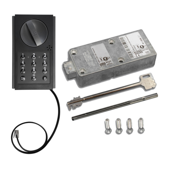
82132/33 Code-Combi B with Plastic Control Unit
Lock mounting position
Lock mounting position
Seite 1 von 10
Advertisement

Related Manuals for Kaba Mauer 82132

Summary of Contents for Kaba Mauer 82132
- Page 1 Mounting Instructions 82132/33 Code-Combi B with Plastic Control Unit 1 General These mounting instructions are the basis for the approval by ECBS, VdS, A2P (CNPP), DNV or UL. Installation of the lock exclusively in accordance with these instructions. Guidelines of the national certification bodies are to be considered and complied with in addition.
- Page 2 Use of the Kaba Mauer key guide (see Fig. 1) is recommended. Considering DIN 2768-mH, the keyhole in the door of the secure storage unit should be dimensioned accordingly (see Fig. 1).
- Page 3 For installation and adjustment of the lock on the door, make sure that the key can be inserted into the lock without having to apply force and without jamming. This can be achieved by mounting the lock according to the following pattern of mounting holes (Fig. 3). For further lock dimensions please refer to the Kaba Mauer Catalogue Sheet. 66,7 Fig.
- Page 4 Mounting Instructions 82132/33 Code-Combi B with Plastic Control Unit 4 Cabling Connectors to be plugged in as follows: Marking on the lock case Cable connection for Marked „input unit“ 6-pole connecting cable to the electronic input system Marked „power“...
-
Page 5: Assembly Drawings
Mounting Instructions 82132/33 Code-Combi B with Plastic Control Unit 6 Assembly drawings 6.1 82132/33 Code-Combi B with plastic control unit 98851/0001 Lock mounting position Control unit mounting position Cable gland ⍁ 10 mm or Ø 11,25 ± 0,05 mm 23,5... - Page 6 Mounting Instructions 82132/33 Code-Combi B with Plastic Control Unit 6.2 82132/33 Code-Combi B with plastic control unit 98851/0002 Lock mounting position Control unit mounting position Cable gland ⍁ 10 mm or Ø 11,25 ± 0,05 mm 23,5 83 ,5 Door penetrations...
- Page 7 Mounting Instructions 82132/33 Code-Combi B with Plastic Control Unit 6.3 82132/33 Code-Combi B with plastic control unit 98852/0001 Lock mounting position Control unit mounting position Cable gland ⍁ 10 mm or Ø 11,25 ± 0,05 mm Door penetrations Keyhole (in lock)
- Page 8 Mounting Instructions 82132/33 Code-Combi B with Plastic Control Unit 6.4 82132/33 Code-Combi B with plastic control unit 98852/0002 Lock mounting position Control unit mounting position Door penetrations Cable gland ⍁ 10 mm or Ø 11,25 mm ± 0,05 mm Keyhole (in lock)
- Page 9 Mounting Instructions 82132/33 Code-Combi B with Plastic Control Unit 6.5 82132/33 Code-Combi B with plastic control unit 98852/0003 Lock mounting position Control unit mounting position Cable gland ⍁ 10 mm or Ø 11,25 mm ± 0,05 mm Door penetrations Keyhole (in lock)
- Page 10 Mounting Instructions 82132/33 Code-Combi B with Plastic Control Unit 6.6 82132/33 Code-Combi B with plastic control unit 98852/0004 Lock mounting position Control unit mounting position Cable gland ⍁ 10 mm or Ø 11,25 mm ± 0,05 mm Door penetrations Keyhole (in lock)
Need help?
Do you have a question about the 82132 and is the answer not in the manual?
Questions and answers