Advertisement
Quick Links
MOD9200BNT BACnet MSTP
NETWORK TRANSCEIVER
Installation & Operation Instructions
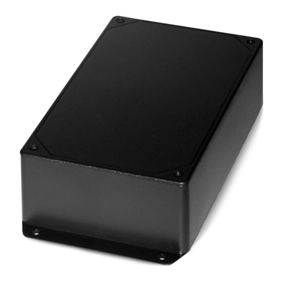
FIGURE 1: ENCLOSURE DIMENSIONS
FRONT VIEW
24 V
TB1
3.50"
(88.90 mm)
4.72"
(119.89mm)
Do not use this product in any safety related applications where human life may be affected.
GENERAL INFORMATION
ACI's Wireless Series MOD9200BNT BACnet® network transceiver utilizes reliable Spread Spectrum Mesh
Network Radio technology. Together with other ACI wireless sensors and controls, the system can be used
to transmit remote sensor readings, status/alarm indications, control signals and outputs wirelessly. It is
compatible with any control panels or Automation Systems that utilize BACnet MSTP (Master Slave Token
Passing) communication protocol. Up to 50 separate physical wireless sensor transmitters and/or wireless
remote output (analog & digital) modules can be used with one MOD9200BNT Transceiver and up to 100
data points and 100 outputs can be monitored and controlled with one (1) MOD9200 Transceiver.
The maximum radio transmission distance is dependent on the building type. In a typical commercial
building with steel I-Beam construction, concrete oors with reinforcing rod, and metal stud walls, it can
be expected that transmissions will penetrate horizontally approximately 200-300 feet of oor, walls,
furniture and air.
RR2552 signal repeaters can be installed as needed to increase transmission distance between sensors and
receivers - see FIGURE 2 (p. 2). Generally, a wireless system will cover at least three oors–one oor above,
and one oor below the receiver location. In some buildings with favorable transmission characteristics the
system may cover more oors - see FIGURE 3 (p. 2). Wireless sensor transmitters should be installed within
200 to 300 feet of the MOD9200 transceiver.
PRECAUTIONS
• To maintain high performance, do not install sensors, repeaters, or receivers in the following areas:
- Inside metal enclosure / panel
- Inside or immediately next to elevator shaft or elevator banks
- In front of or immediately next to large trees or large body of water
Automation Components, Inc.
2305 Pleasant View Road | Middleton, WI 53562
Phone: 1-888-967-5224 | Website: workaci.com
8.26"
(209.80 mm)
Init
Norm
J2
RJ45
A(+)
B(-)
SHLD
RS232
A(+)
B(-)
J1
8.78"
(223 mm)
DATA LINK
LED
ACTIVE LED
ANTENNA
Page 1
Phone: 1-888-967-5224
Website: workaci.com
SIDE PROFILE
Ø: 0.190" (4 PLCS.)
7.63"
(184.50 mm)
FRONT
(60.10 mm)
Version: 8.0
I0000668
2.37"
Advertisement

Related Manuals for aci MOD9200BNT


Summary of Contents for aci MOD9200BNT
- Page 1 Passing) communication protocol. Up to 50 separate physical wireless sensor transmitters and/or wireless remote output (analog & digital) modules can be used with one MOD9200BNT Transceiver and up to 100 data points and 100 outputs can be monitored and controlled with one (1) MOD9200 Transceiver.
- Page 2 MOUNTING INSTRUCTIONS Mount the MOD9200BNT near MSTP access point, 1’ below the ceiling, using four #8 screws. FIGURE 2: WIRELESS BUILDING DIAGRAM REPEATER & RECEIVER 1’ FROM CEILING RECEIVER SENSOR REPEATER FIGURE 3: WIRELESS MULTILEVEL DIAGRAM WIRING INSTRUCTIONS WIRING PRECAUTIONS •...
- Page 3 “A&B” terminals - see FIGURE 4 (top). If the MOD9200BNT is in the middle of the bus and needs to be daisy chained, both sets of “A” and “B” terminals...
- Page 4 Flammability Rating: WARRANTY The ACI Wireless Series are covered by ACI’s Two (2) Year Limited Warranty, which is located in the front of ACI’S SENSORS & TRANSMIT TERS CATALOG or can be found on ACI’s website: www.workaci.com. W.E.E.E. DIRECTIVE At the end of their useful life the packaging and product should be disposed of via a suitable recycling centre.
Need help?
Do you have a question about the MOD9200BNT and is the answer not in the manual?
Questions and answers