Table of Contents
Advertisement
Quick Links
WARNING
Before servicing any valve, you
must depressurize the system
and cycle the valve. Residual
material may be left
in the valve and system.
Disassembly
End Screws
1. Remove both end screws (17) from valve body
(3) and separate the seat carrier assembly (11)
from end screws.
2. Discard the following components: Seat carrier assemblies
(11), seat springs (12), seat carrier glands (13), carrier
backup rings (14), seat carrier O-rings (15), and end
screw seals (16).
Ball and Stem
3. Straight pattern only - remove plug (18) from bottom
of valve body (3). Clean components and set aside for
later re-installation.
4. Remove the set screw in handle (1) and remove handle.
For X-pattern assemblies, note the position of the handle
for reassembly.
5. Remove the ball (9) assembly through the bottom
of the valve body (3). For X-pattern assemblies, note
the position of the ball orifice for reassembly. Discard
the ball (9) and trunnion bearings (8). The ball must
also be replaced to ensure a leak-tight seal with the
new seat assemblies.
6. Remove stem (4) through bottom of the valve
body by pressing down on the top of the stem.
7. Remove and discard the stem O-ring (5), stem
back-up rings (6), stem secondary back-up ring
(7), stem bearing (8) and stem (4).
8. Remove all lubricants and
contaminants from the valve body.
Reassembly
Seat Carrier Subassembly (two per valve)
1. PEEK SEATS - Assemble six seat springs (12) onto the
shaft of the seat carrier (11) in three groups of two.
The first two springs should be assembled "concave
out" with the concave side facing away from the head
of the seat carrier, the next two concave in, and the
final two concave out.
2. PTFE SEATS - Assemble three seat springs (12) onto the
shaft of the seat carrier (11). The first spring should be
assembled "concave out" with the concave side facing
2-Way
3
2
18
10
9
Maintenance Instructions
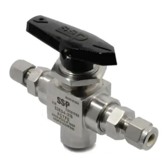
TB & TBX Series Ball Valve
Kit Contents
Seat Carrier Assembly (2)
Seat Carrier O-Ring (2)
Seat Springs (6 or 12)
Stem
Stem Bearing
Stem O-Ring
away from the head of the seat carrier, the next
spring concave in, and the final spring concave out.
3. Assemble the carrier gland (13) onto the shaft of the
seat carrier.
4. Lightly lube one carrier back-up ring (14) with
LT-CL-111 lubricant and assemble it onto the
shaft of the seat carrier.
5. Lightly lube the carrier O-ring (15) with
LT-CL-111 lubricant and assemble it onto
the shaft of the seat carrier.
6. Lightly lube a second carrier back-up ring (14) with
LT-CL-111 lubricant and assemble it onto the shaft
of the seat carrier on the other side of the O-ring.
Stem Subassembly (one per valve)
1. Lightly lube the stem back-up rings (6), the secondary
stem back-up ring (7), the stem O-ring (5) and the stem
bearing (8) with LT-CL-111 lubricant.
2. Assemble the stem bearing (8) onto the
stem (4) so that it rests flush against the hub.
3. Assemble the stem O-ring (5) into the
lower (widest) groove on the stem.
4. Assemble the stem back-up ring (6) onto the stem
in the lower groove just above the stem O-ring (5).
5. Assemble the stem secondary back-up ring (7)
onto the stem in the lower groove just above
the primary stem back-up ring.
6. Assemble a second stem back-up ring (6) onto
the stem in the upper (narrowest) groove.
Ball Subassembly (one per valve)
1. Lightly lube the trunnion bearings (10) with
LT-CL-111 lubricant and assemble them into
the grooves in the trunnions of the ball (9).
End screw Subassembly (two per valve)
1. Clean all lubricants and/or contamination
from the end screws (17) (reusable).
3. Insert one of the finished seat carrier
subassemblies (11-15),
1
16
13
15
11
14
17
12
4
6
7
5
8
Stem Back-up Ring (2)
Stem Secondary Back-up Ring
Trunnion Bearing
Carrier Back-up Ring (4)
Carrier Gland (2)
Ball
3-Way
Item
Components
1
Handle
2
Panel Nut
3
Body
4
Stem
5
Stem O-Ring
6
Stem Back-Up Ring
Stem Secondary
7
Back-up Ring
8
Stem Bearing
9
Ball
10
Trunnion Bearing
11
Seat Carrier Assembly
12
Seat Springs
13
Seat Carrier Gland
14
Carrier Back-up Rings
15
Carrier O-Ring
16
End Screw Seal
17
End Screw
18
Plug (2-Way Only)
End Screw Seal (2)
Lubricant
Material Safety Data Sheet
Instruction Sheet
shaft end first, into the main bore of the end screw.
The seat spring stack will make contact with the face
of the end screw when the seat carrier subassembly
is fully inserted.
2. Lightly lube the end screw seal (16) with LT-CL-111
lubricant and assemble onto the nose of the end
screw (17).
Valve Assembly
1. Insert the stem subassembly (4-8) up through the bottom
of the valve body (3). A blunt instrument may be used to
insure that the stem subassembly is fully seated against
the internal shoulder of the body bore. Care must be
taken when installing the stem into the body to prevent
scoring of the body bore or clipping of the stem O-ring
(5). The stem flats should be parallel to the end screw
holes and the stem hole should be facing the front
of the valve body allowing for proper alignment with
the handle (1).
2. Assemble the Handle (1) onto the stem (4) and attach it
firmly with the set screw. The handle can only be installed
on the stem in one direction.
3. Insert the ball subassembly (tang end up) into the bottom
bore of the valve body. Push the ball into the valve body
until the ball tangs engage the stem slot. Rotate the
handle to insure that the ball tang is engaged in the stem
slot. Be certain that the X-pattern ball orifice is facing the
same direction as the handle (1) flow arrow.
4. Valve handle must be placed in the fully closed position
(straight pattern) or center-off (X-pattern) to prevent seat
damage when torqueing the end screws.
5. Moderately lube the threads of the end screw
subassemblies (11-17) and insert them into the side
bores of the body. Torque each end screw subassembly
to 500 in·lbs (56.5 N·m).
6. Straight pattern valve assemblies only: Wrap plug (18)
with two complete wraps of PTFE tape or use system
compatible thread sealant. Install plug in bottom port
of valve body and torque to 300 in·lbs (33.9 N·m).
1
3
11
2
10
9
7
5
8
16
13
15
14
17
12
4
6
Advertisement
Table of Contents

Related Manuals for SSP TB Series


Summary of Contents for SSP TB Series
- Page 1 Maintenance Instructions TB & TBX Series Ball Valve Kit Contents WARNING Seat Carrier Assembly (2) Stem Back-up Ring (2) Before servicing any valve, you End Screw Seal (2) Seat Carrier O-Ring (2) Stem Secondary Back-up Ring must depressurize the system and cycle the valve.
- Page 2 Panel Nut Body Stem Stem O-Ring Stem Back-Up Ring Stem Secondary Back-up Ring Stem Bearing Ball Trunnion Bearing Seat Carrier Assembly Seat Springs Seat Carrier Gland Carrier Back-up Rings Carrier O-Ring End Screw Seal End Screw Plug (2-Way Only) www.my-ssp-usa.com TBTBXMI-20170411-A...
Need help?
Do you have a question about the TB Series and is the answer not in the manual?
Questions and answers