Table of Contents
Advertisement
Advertisement
Table of Contents

Related Manuals for Lenovo Yoga A940


Summary of Contents for Lenovo Yoga A940
- Page 1 Yoga A940 Hardware Maintenance Manual Machine Types (MT): F0E4 and F0E5...
- Page 2 “Read this first: Important safety information” on page 1. First Edition (December 2018) © Copyright Lenovo 2018. LIMITED AND RESTRICTED RIGHTS NOTICE: If data or software are delivered pursuant to a General Services Administration “GSA” contract, use, reproduction, or disclosure is subject to restrictions set forth in Contract No. GS-...
-
Page 3: Table Of Contents
Major FRUs and CRUs ... . Trademarks ....1 Parts on the system boards ..© Copyright Lenovo 2018... - Page 4 Yoga A940Hardware Maintenance Manual...
-
Page 5: About This Manual
Important: This manual is intended only for trained service technicians who are familiar with Lenovo computers. Use this manual along with the advanced diagnostic tests to troubleshoot problems effectively. Before servicing a Lenovo computer, be sure to read and understand Chapter 1 “Read this first: Important safety information” on page 1. - Page 6 Yoga A940Hardware Maintenance Manual...
-
Page 7: Chapter 1. Read This First: Important Safety Information
• Reattach all covers correctly before returning the computer to the customer. Electrical safety CAUTION: Electrical current from power, telephone, and communication cables can be hazardous. To avoid personal injury or equipment damage, disconnect any attached power cords, telecommunication © Copyright Lenovo 2018... - Page 8 cables, network cables, and modem cables before you open the computer covers, unless instructed otherwise in the installation and configuration procedures. Observe the following rules when working on electrical equipment. Important: Use only approved tools and test equipment. Some hand tools have handles covered with a soft material that does not insulate you when working with live electrical currents.
-
Page 9: Safety Inspection Guide
• If an electrical accident occurs: – Use caution; do not become a victim yourself. – Switch off power. – Send another person to get medical aid. Safety inspection guide The intent of this inspection guide is to assist you in identifying potential hazards posed by these products. Each computer, as it was designed and built, had required safety items installed to protect users and service personnel from injury. -
Page 10: Grounding Requirements
1. Use product-specific ESD procedures when they exceed the requirements noted here. 2. Make sure that the ESD protective devices you use have been certified (ISO 9000) as fully effective. When handling ESD-sensitive parts: • Keep the parts in protective packages until they are inserted into the product. •... - Page 11 • Connect and disconnect cables as described in the following table when installing, moving, or opening covers on this product or attached devices. To Connect To Disconnect 1. Turn everything OFF. 1. Turn everything OFF. 2. First, attach all cables to devices. 2.
- Page 12 ≥18 kg (37 lbs) ≥32 kg (70.5 lbs) ≥55 kg (121.2 lbs) CAUTION: Use safe practices when lifting. CAUTION: The power control button on the device and the power switch on the power supply do not turn off the electrical current supplied to the device. The device also might have more than one power cord. To remove all electrical current from the device, ensure that all power cords are disconnected from the power source.
-
Page 13: Chapter 2. Environment And Electrical Input
Operating: From -15.2 m (-50 ft) to 3048 m (10 000 ft) Storage: From -15.2 m (-50 ft) to 10 668 m (35 000 ft) Electrical input Input voltage: For PSU400W, 200 – 240 VAC; For PSU 450W/280W, 100 – 240 VAC Input frequency: 50/60 Hz © Copyright Lenovo 2018... - Page 14 Yoga A940Hardware Maintenance Manual...
-
Page 15: Chapter 3. General Checkout
• If the computer displays a POST error, go to “POST error codes”. • If the computer hangs and no error is displayed, proceed to step 7. 7. If the test stops and you cannot continue, replace the last device tested. © Copyright Lenovo 2018... - Page 16 Yoga A940Hardware Maintenance Manual...
-
Page 17: Chapter 4. Using The Setup Utility Program
5. Exit the Setup Utility program. See “Exiting the Setup Utility program” on page 13. Using BIOS passwords By using the Setup Utility program, you can set passwords to prevent unauthorized access to your computer and data. © Copyright Lenovo 2018... -
Page 18: Setup Utility Program Password Types
You do not have to set all passwords to use your computer. However, using passwords improves computer security. Setup Utility program password types The following types of passwords are available: • Power-on password When a power-on password is set, you are prompted to enter a valid password each time the computer is turned on. -
Page 19: Changing The Startup Device Sequence Permanently
Changing the startup device sequence permanently To change the startup device sequence permanently, do the following: 1. Depending on the type of the storage device, do one of the following: • If the storage device is internal, go to step 2. •... - Page 20 Yoga A940Hardware Maintenance Manual...
-
Page 21: Chapter 5. Symptom-To-Fru Index
Reseat connectors Check that the following are properly installed: • Power Cord • On/Off Switch connector • System Board Power Supply connectors • Microprocessor connections Check the power cord. Power Cord Check the power-on switch. Power-on Switch © Copyright Lenovo 2018... -
Page 22: Post Error Codes
POST error codes Each time you turn the computer on, it performs a series of tests to check that the system is operating correctly and that certain options are set. This series of tests is called the Power-On Self-Test, or POST. POST does the following: •... -
Page 23: Chapter 6. Hardware Locations
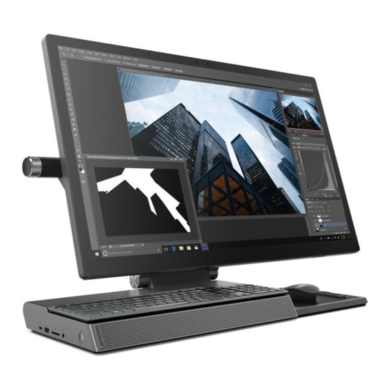
Attention: Be careful not to block any air vents on the computer. Blocked air vents can cause overheating. Figure 1. Front view Microphones Camera indicator Camera cover slider Camera (standard or Windows Hello compatible) Display (with multi-touch function) Speakers (with Bluetooth connectivity) © Copyright Lenovo 2018... - Page 24 Figure 2. Rear view Air vents Monitor/computer mode switch Power connector Ethernet connector HDMI in/out connector USB 3.1 Gen 1 connectors Figure 3. Left view and right view USB 2.0 connector Thunderbolt 3 (USB-C) connector Memory card slot USB 3.1 Gen 2 connector Yoga A940Hardware Maintenance Manual...
- Page 25 Combo audio jack Power button (with indicator) LED lamp Speakers LED lamp button Figure 4. Peripheral devices Lenovo Dial Wireless mouse and keyboard Wireless charging pad Lenovo Digital Pen Chapter 6 Hardware locations...
-
Page 26: Major Frus And Crus
Major FRUs and CRUs Note: Depending on your computer model, some of the following components might not be available. The following table lists the major FRUs shown in the illustration above and identifies which FRUs are also self-service CRUs or optional-service CRUs. Notes: •... - Page 27 Figure 6. overview Chapter 6 Hardware locations...
- Page 28 HDD bracket Bluetooth speaker board Wireless charger LED board Wireless charger cover Lenovo Digital Pen Wireless charger module System housing assembly Base holder assembly For detailed FRU information, such as the FRU part numbers and supported computer models, go to: http:// www.lenovo.com/serviceparts-lookup...
-
Page 29: Parts On The System Boards
Parts on the system boards Parts on the system board Figure 7. Parts on the system board HDMI switch board connector WTB for DC-IN connector Power connector RJ45 connector HDMI connector USB 3.1 Gen 1 connector USB 3.1 Gen 1 connector USB 3.1 Gen 1 connector USB 3.1 Gen 1 connector Thunderbolt 3 (USB-C) connector... - Page 30 Yoga A940Hardware Maintenance Manual...
-
Page 31: Chapter 7. Installing Or Replacing Hardware
• When installing or replacing an option, use the appropriate instructions in this section along with the instructions that come with the option. • In most areas of the world, Lenovo requires the return of the defective CRU. Information about this will come with the CRU or will come a few days after the CRU arrives. - Page 32 • For this procedure, it is helpful to lay the computer on a flat, stable and wide surface. • Make sure the surface is clean and dry. CAUTION: Before you open the computer covers, turn off the computer and wait several minutes until the computer is cool.
- Page 33 Figure 9. Removing screws 5. Detach 4 connectors and carefully take the computer base off the display panel Figure 10. Removing the display panel What to do next: • To work with another piece of hardware, go to the appropriate section. •...
-
Page 34: Replacing The Usb Connector
Replacing the USB connector Make sure the following FRUs (or CRUs) have been removed. “Replacing the computer display panel” on page 25 To remove the USB connector, do the following: 1. Detach 2 connectors and remove 4 screws Figure 11. Detaching connectors and releasing screws 2. -
Page 35: Replacing The Wi-Fi Card
To remove the function board shield, do the following: 1. Detach 2 connectors and remove 3 screws 2. Remove the function board shield Figure 13. Removing the function board shield What to do next: • To work with another piece of hardware, go to the appropriate section. •... -
Page 36: Replacing The Function Board
Figure 14. Removing the Wi-Fi cover 2. Detach 2 connectors and remove the Wi-Fi card Figure 15. Removing the Wi-Fi card What to do next: • To work with another piece of hardware, go to the appropriate section. • To complete the installation or replacement, go to “Completing the parts replacement” on page 55. Replacing the function board Make sure the following FRUs (or CRUs) have been removed. -
Page 37: Replacing The Touch Board Shield
Figure 16. Removing screws and detaching connectors 2. Remove the function board Figure 17. Removing the function board What to do next: • To work with another piece of hardware, go to the appropriate section. • To complete the installation or replacement, go to “Completing the parts replacement” on page 55. Replacing the touch board shield Make sure the following FRUs (or CRUs) have been removed. -
Page 38: Replacing The Touch Board
Figure 18. Removing the touch board shield What to do next: • To work with another piece of hardware, go to the appropriate section. • To complete the installation or replacement, go to “Completing the parts replacement” on page 55. Replacing the touch board Make sure the following FRUs (or CRUs) have been removed. -
Page 39: Replacing The Subwoofer
Figure 20. Removing the touch board What to do next: • To work with another piece of hardware, go to the appropriate section. • To complete the installation or replacement, go to “Completing the parts replacement” on page 55. Replacing the subwoofer Make sure the following FRUs (or CRUs) have been removed. -
Page 40: Replacing The Led Light Bar
Figure 22. Removing the subwoofer What to do next: • To work with another piece of hardware, go to the appropriate section. • To complete the installation or replacement, go to “Completing the parts replacement” on page 55. Replacing the LED light bar Make sure the following FRUs (or CRUs) have been removed. - Page 41 “Replacing the computer display panel” on page 25 “Replacing the USB connector” on page 28 “Replacing the function board shield” on page 28 “Replacing the function board” on page 30 “Replacing the touch board shield” on page 31 “Replacing the touch board” on page 32 “Replacing the subwoofer”...
-
Page 42: Replacing The Microphone Module And The Camera Module
• To complete the installation or replacement, go to “Completing the parts replacement” on page 55. Replacing the microphone module and the camera module Make sure the following FRUs (or CRUs) have been removed. “Replacing the computer display panel” on page 25 “Replacing the USB connector”... -
Page 43: Replacing The Mainframe
Figure 27. Detaching connectors What to do next: • To work with another piece of hardware, go to the appropriate section. • To complete the installation or replacement, go to “Completing the parts replacement” on page 55. Replacing the mainframe Make sure the following FRUs (or CRUs) have been removed. -
Page 44: Replacing The Front Bezel
Figure 28. Removing the mainframe What to do next: • To work with another piece of hardware, go to the appropriate section. • To complete the installation or replacement, go to “Completing the parts replacement” on page 55. Replacing the front bezel Make sure the following FRUs (or CRUs) have been removed. -
Page 45: Replacing The Memory Module
Figure 30. Removing the system housing top What to do next: • To work with another piece of hardware, go to the appropriate section. • To complete the installation or replacement, go to “Completing the parts replacement” on page 55. Replacing the memory module Make sure the following FRUs (or CRUs) have been removed. -
Page 46: Replacing The Ssd
Replacing the SSD Make sure the following FRUs (or CRUs) have been removed. “Replacing the computer display panel” on page 25 “Replacing the front bezel” on page 38 To remove the SSD, do the following: 1. Remove 1 screw Figure 32. Removing the screw 2. -
Page 47: Replacing The Cmos Battery
“Replacing the computer display panel” on page 25 “Replacing the front bezel” on page 38 To remove the fan, do the following: 1. Remove 3 screws and detach 1 connector Figure 34. Removing screws and detaching the connector 2. Remove the fan Figure 35. -
Page 48: Replacing The Speakers
“Replacing the fan” on page 40 “Replacing the thermal module” on page 45 To remove the CMOS battery the following: 1. Remove the CMOS battery Figure 36. Removing the CMOS battery What to do next: • To work with another piece of hardware, go to the appropriate section. •... -
Page 49: Replacing The Housing Top Metal Assembly
Figure 37. Removing the speakers 2. Remove the speakers Figure 38. Removing the speakers What to do next: • To work with another piece of hardware, go to the appropriate section. • To complete the installation or replacement, go to “Completing the parts replacement” on page 55. Replacing the housing top metal assembly Make sure the following FRUs (or CRUs) have been removed. -
Page 50: Replacing The Fan Duct
Figure 39. Removing screws 2. Remove the housing top metal assembly Figure 40. Removing the housing top metal assembly What to do next: • To work with another piece of hardware, go to the appropriate section. • To complete the installation or replacement, go to “Completing the parts replacement” on page 55. Replacing the fan duct Make sure the following FRUs (or CRUs) have been removed. -
Page 51: Replacing The Thermal Module
Figure 41. Removing screws 2. Remove the fan duct Figure 42. Removing the fan duct What to do next: • To work with another piece of hardware, go to the appropriate section. • To complete the installation or replacement, go to “Completing the parts replacement” on page 55. Replacing the thermal module Make sure the following FRUs (or CRUs) have been removed. -
Page 52: Replacing The Cpu
Figure 43. Loosening and removing screws 2. Remove the thermal module Figure 44. Removing the thermal module What to do next: • To work with another piece of hardware, go to the appropriate section. • To complete the installation or replacement, go to “Completing the parts replacement” on page 55. Replacing the CPU Make sure the following FRUs (or CRUs) have been removed. -
Page 53: Replacing The Hdd
2. Lift the CPU straight up and out of the socket Figure 45. Removing the CPU What to do next: • To work with another piece of hardware, go to the appropriate section. • To complete the installation or replacement, go to “Completing the parts replacement” on page 55. Replacing the HDD Make sure the following FRUs (or CRUs) have been removed. -
Page 54: Replacing The Hdd Sata Connector
What to do next: • To work with another piece of hardware, go to the appropriate section. • To complete the installation or replacement, go to “Completing the parts replacement” on page 55. Replacing the HDD SATA connector Make sure the following FRUs (or CRUs) have been removed. “Replacing the computer display panel”... -
Page 55: Replacing The Power Button Board
To remove the system board, do the following: 1. Remove 6 screws Figure 48. Removing the system board 2. Remove the system board Figure 49. Removing the system board What to do next: • To work with another piece of hardware, go to the appropriate section. •... -
Page 56: Replacing The Hdmi Switch Board
Figure 50. Removing the power button board What to do next: • To work with another piece of hardware, go to the appropriate section. • To complete the installation or replacement, go to “Completing the parts replacement” on page 55. Replacing the HDMI switch board Make sure the following FRUs (or CRUs) have been removed. -
Page 57: Replacing The Wireless Charger Cover
What to do next: • To work with another piece of hardware, go to the appropriate section. • To complete the installation or replacement, go to “Completing the parts replacement” on page 55. Replacing the wireless charger cover Make sure the following FRUs (or CRUs) have been removed. “Replacing the computer display panel”... -
Page 58: Replacing The Wireless Charger Led Board
1. Detach 1 connector and remove 1 screw Figure 53. Detaching 1 connector and removing 1 screw 2. Remove the Bluetooth speaker board Figure 54. Removing the Bluetooth speaker board What to do next: • To work with another piece of hardware, go to the appropriate section. •... -
Page 59: Replacing The Wireless Charger Module
“Replacing the HDD” on page 47 “Replacing the wireless charger cover” on page 51 To remove the wireless charger LED board, do the following: 1. Remove 1 screw and detach 1 connector Figure 55. Removing the wireless charger LED board 2. - Page 60 “Replacing the front bezel” on page 38 “Replacing the speakers” on page 42 “Replacing the housing top metal assembly” on page 43 “Replacing the HDD” on page 47 “Replacing the wireless charger cover” on page 51 To remove the wireless charger module, do the following: 1.
-
Page 61: Completing The Parts Replacement
Completing the parts replacement To reinstall the computer covers and reconnect cables to your computer, do the following: 1. Ensure that all components have been reassembled correctly and that no tools or loose screws are left inside your computer. See Chapter 6 “Hardware locations” on page 17 for the locations of various components in your computer. - Page 62 Yoga A940Hardware Maintenance Manual...
-
Page 63: Chapter 8. Additional Service Information
• Wake Up on Alarm: You can specify a date and time at which the computer will be turned on automatically. This can be either a single event , a daily event or a weekly event. • Wake Up on LAN: This feature allows LAN adapter card to wake the System. © Copyright Lenovo 2018... - Page 64 Yoga A940Hardware Maintenance Manual...
-
Page 65: Trademarks
Trademarks The following terms are trademarks of Lenovo in the United States, other countries, or both: Lenovo The Lenovo logo Yoga Windows is a trademark of the Microsoft group of companies. Other company, product, or service names may be trademarks or service marks of others.
Need help?
Do you have a question about the Yoga A940 and is the answer not in the manual?
Questions and answers