3Com 4800G Getting Started Manual
3com 4800g: install guide
Hide thumbs
Also See for 4800G:
- Datasheet (8 pages) ,
- Configuration manual (1246 pages) ,
- Product manual (15 pages)

Subscribe to Our Youtube Channel
Related Manuals for 3Com 4800G


Summary of Contents for 3Com 4800G
- Page 1 ® 3Com Switch 4800G Family Getting Started Guide Switch 4800G 24-Port Switch 4800G PWR 24-Port Switch 4800G 48-Port Switch 4800G PWR 48-Port Switch 4800G 24-Port SFP www.3Com.com Part Number: 10016617 Rev AA Published: April 2008...
- Page 2 LICENSE.TXT or !LICENSE.TXT. If you are unable to locate a copy, please contact 3Com and a copy will be provided to you.
-
Page 3: Table Of Contents
VERVIEW Introduction Switch 4800G 24-Port Switch 4800G PWR 48-Port Switch 4800G PWR 24-Port Switch 4800G 24-Port SFP Switch 4800G 48-Port System Specifications of the Switch 4800G Series Pluggable Modules Optional Interface Modules CX4 Cable REPARATING TO NSTALL THE Safety Precautions... - Page 4 Installating the Lightning Arrester for AC Power (Socket Strip with Lightning Protection) Installation of Lightning Arrester for Network Port ETWORK ANAGEMENT 3Com Network Supervisor 3Com Network Director 3Com Network Access Manager 3Com Enterprise Management Suite Integration Kit with HP OpenView Network Node Manager OFTWARE ROUBLESHOOTING WITCH...
-
Page 5: Bout This Guide
(LAN) operations and familiarity with communication protocols that are used to interconnect LANs. Always download the Release Notes for your product from the 3Com World Wide Web site and check for the latest updates to software and product documentation: http://www.3com.com... - Page 6 If information in this guide differs from information in the release notes, use the information in the Release Notes. These documents are available in Adobe Acrobat Reader Portable Document Format (PDF) on the CD-ROM that accompanies your router or on the 3Com World Wide Web site: http://www.3com.com/...
-
Page 7: Product Overview
The Switch 4800G are designed to operate at the convergence or access layer of enterprise networks and metropolitan area networks (MANs). The Switch 4800G support the IPv4/IPv6 dual stack and can also be used for connecting server groups in data centers. -
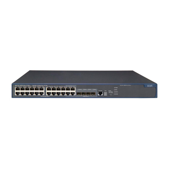
Page 8: Switch 4800G 24-Port
VERVIEW Table 3 Mapping between two ports forming a Combo port Model Switch 4800G 48-Port For the convenience of monitoring the running of the Switch 4800G, LEDs are also equipped on their front panel. Switch 4800G 24-Port Appearance The Switch 4800G 24-Port provides twenty-four auto-sensing 10/100/1000BASE-T... -
Page 9: Rear Panel
(1) AC power socket (3) Grounding screw (5) Extended module slot 2 Power Supply System The Switch 4800G 24-Port can adopt AC input, or 12 V RPS input, or both to provide backup. Only the recommended RPS can be used. ■ ■... - Page 10 1: P HAPTER RODUCT VERVIEW Table 4 LEDs on the front panel of the Switch 4800G 24-Port Mark Status Redundant power Solid green system LED Solid yellow Module LED Solid green Flashing yellow 7-segment digital LED Unit POST running POST failed...
-
Page 11: Switch 4800G Pwr 48-Port
Table 4 LEDs on the front panel of the Switch 4800G 24-Port Mark Status 10/100/1000Base-T Speed port status LED Duplex SFP port status LED The Mode button has no (1000 Mbps) effect on the LED. SFP port status LED Speed... -
Page 12: Front Panel
(3) Grounding screw (5) Extended module slot 2 Power Supply System The Switch 4800G PWR 48-Port can adopt AC input, or 12V RPS input, or both to provide backup. Only the recommended RPS can be used. AC power input ■... -
Page 13: Switch 4800G Pwr 24-Port
The Switch 4800G PWR 48-Port is equipped with four fans for heat dissipation. LEDs The LEDs on the front panel of the Switch 4800G PWR 48-Port are the same as those of the Switch 4800G 24-Port. For details, see Table 4. - Page 14 Figure 9 Rear panel of the Switch 4800G PWR 24-Port (1) RPS port (3) Grounding screw (5) Extended module slot 2 Power Supply System The Switch 4800G PWR 24-Port can adopt AC power input, or DC power input, or both to provide backup. ■ ■ Cooling System The Switch 4800G PWR 24-Port is equipped with six fans for heat dissipation.
- Page 15 Table 5 Descriptions of the LEDs on the front panel of Switch 4800G PWR 24-Port Mark Status Redundant power Solid green system LED Solid yellow Module LED Solid green Flashing yellow 7-segment digital Unit POST running POST failed Software loading...
- Page 16 1: P HAPTER RODUCT VERVIEW Table 5 Descriptions of the LEDs on the front panel of Switch 4800G PWR 24-Port Mark Status 10/100/1000Base-T Speed Ethernet port status Duplex SFP port status LED The Mode button has no (1000 Mbps) effect on the LED.
-
Page 17: Switch 4800G 24-Port Sfp
Figure 11 shows the appearance of the Switch 4800G 24-Port SFP. Figure 10 Appearance of the Switch 4800G 24-Port SFP Front Panel Figure 11 Front panel of the Switch 4800G 24-Port SFP (1) Auto-sensing 10/100/1000Base-T Ethernet port status LEDs (2) Console port (4) Mode button... -
Page 18: Switch 4800G 48-Port
The Switch 4800G 24-Port SFP is equipped with six fans for heat dissipation. LEDs The LEDs on the front panel of the Switch 4800G 24-Port SFP are the same as those of the Switch 4800G PWR 24-Port. For details, see Table 5. -
Page 19: Power System
Rated voltage range: -48 VDC to -60 VDC Input voltage range: -36 VDC to -72 VDC Cooling System The Switch 4800G 48-Port is equipped with six fans (four for the system, and one for each power module) for heat dissipation. LEDs For descriptions about LEDs, see Table 6. - Page 20 1: P HAPTER RODUCT VERVIEW Table 6 Description of LEDs on the front panel of the Switch 4800G 48-Port Mark Status Mode LED Mode Speed Duplex Solid yellow System power LED Solid green Flashing green (1 Hz) Solid red Flashing yellow (1 Hz)
- Page 21 Table 6 Description of LEDs on the front panel of the Switch 4800G 48-Port Mark Status 7-segment digital Unit POST running POST failed Software loading Fan failure Over-temperature alarm Cluster status Auto-sensing Speed 10/100/1000Base-T Ethernet port status Duplex SFP port status LED...
-
Page 22: System Specifications Of The Switch 4800G Series
1: P HAPTER RODUCT VERVIEW Table 6 Description of LEDs on the front panel of the Switch 4800G 48-Port Mark Status SFP port status LED Speed (100 Mbps) Duplex System Specifications of the Switch 4800G Series Table 7 System specifications of the Switch 4800G... -
Page 23: Optional Interface Modules
Table 8 Pluggable modules that the Switch 4800G support Item SFP module XFP module ■ ■ Optional Interface The Switch 4800G provide two 10 GE interface module slots (extended module Modules slots) on the rear panel. You can select the following interface modules: ■ ■ ■ ■... -
Page 24: Cx4 Cable
CX4 Cable You can use a CX4 cable to connect the CX4 port on the rear panel of the Switch 4800G to another CX4 port. Figure 16 CX4 cable The following three types of CX4 cables are available: ■... -
Page 25: Reparating To Nstall The Switch
■ ■ ■ ■ ■ Installation Site The Switch 4800G must be used indoors. You can mount the switch in a rack or on a workbench, but make sure: ■ ■ ■ ■ To ensure normal operation and long service life of your switch, install it in an environment that meets the requirements described in the following subsections. -
Page 26: Electromagnetic Susceptibility
The Switch 4800G are Class 1 laser devices. CAUTION: When an optional interface module or SFP module on the Switch 4800G is operating, do not stare into the optical port because the laser light emitted from the optical fiber may hurt your eyes. -
Page 27: Installation Tools
Installation Tools ■ ■ ■ CAUTION: The installation tools are not shipped with the Switch 4800G. Flat-module screwdriver Phillips screwdriver ESD-preventive wrist strap Installation Tools... - Page 28 2: P HAPTER REPARATING TO NSTALL THE WITCH...
-
Page 29: Installing The Switch Into A 19-Inch Cabinet
CAUTION: When you ask your sales agent to maintain the switch, you must ensure that the dismantlement-preventive seal on a mounting screw of the 3Com switch chassis is intact. If you want to open the chassis, you should contact the agent for permission. - Page 30 (L1 in Figure 17) according to the physical dimensions. For the selection of front and rear mounting ears, see Table 13. Table 13 Selection of mounting ear for the Switch 4800G Model Switch 4800G 24-Port...
-
Page 31: Introduction To Guide Rails
Introduction to Guide Figure 19 shows the appearance of a guide rail. Rails Figure 19 Appearance of a guide rail Slotted hole 1: Used to fix the guide rail to the rear bracket. You can adjust the screw hole position according to the position of the switch. Cooling hole: Used for heat dissipation between switch and cabinet Slotted hole 2: Used to fix the guide rail to the front bracket Guide rails are optional parts. -
Page 32: Using Front And Rear Mounting Ears
3: I HAPTER NSTALLING THE WITCH Figure 21 Fix front mounting ears (2) Using Front Mounting Follow these steps to install the switch into a 19-inch standard cabinet: Ears and a Tray 1 Wear an ESD-preventive wrist strap to check the grounding and stability of the cabinet. - Page 33 There are three positions to mount a load-bearing screw on both sides of a switch (only two positions on both sides of the Switch 4800G 48-Port). You should select a proper position according to the actual requirements. The rear mounting ears support the switch by tightly contacting with the load-bearing screws.
- Page 34 3: I HAPTER NSTALLING THE WITCH Figure 24 Fix front and rear mounting ears Front mounting ear Screw 1: Used to bear the weight Screw 2: Used to fix rear mounting ears to rear brackets After the switch is pushed into the cabinet, ensure that the upper edge of rear mounting ears is tightly contacted with the load-bearing screw, as shown in Figure 25.
- Page 35 Installing the Switch into a 19-Inch Cabinet Figure 25 Effect diagram of front and rear mounting ear installation (1) Rear panel Rear square-holed bracket Screw 1 Rear mounting ear Screw 1: Load-bearing screw 6 Fix the other end of the front mounting ears to the front brackets with screws and captive nuts and ensure that front and rear mounting ears have fixed the switch in the cabinet securely, as shown in Figure 26.
-
Page 36: Using Front Mounting Ears And Guide Rails
3: I HAPTER NSTALLING THE WITCH Figure 26 Effect diagram of front and rear mounting ear installation (2) Front square-holed bracket Screw 1: Load-bearing screw Using Front Mounting Follow these steps to install a switch into a 19-inch standard cabinet: Ears and Guide Rails 1 Wear an ESD-preventive wrist strap to check the grounding and stability of the cabinet. - Page 37 Figure 27 Install front mounting ears 3 Install guide rails on the brackets on both sides of the cabinet with M5 self-tapping screws, as shown in Figure 28. Figure 28 Install guide rails 4 Hold the two sides of the switch and slide it gently along the guide rails into the cabinet until it is located in a proper position, as shown in Figure 29.
-
Page 38: Mounting The Switch On A Workbench
3: I HAPTER NSTALLING THE WITCH 5 Fix the other end of front mounting ears to the front brackets of the cabinet with M6 screws and captive nuts and ensure that the front mounting ears and guide rails have fixed the switch in the cabinet securely, as shown in Figure 30. Figure 30 Effect diagram of front mounting ear and guide rail installation Ensure a clearance of 1U (44.45 mm or 1.75 inches) between devices for the purpose of heat dissipation. - Page 39 The AC-powered Switch 4800G 24-Port and the Switch 4800G PWR 48-Port use the 12V RPS. The DC-powered Switch 4800G 24-Port uses the 12V RPS or the 48V RPS. For the connection of the 48V RPS power cable, refer to section “Connecting the DC...
- Page 40 Figure 33 Appearance of the 12V RPS socket Pin Number Connect the DC power cable of the Switch 4800G 24-Port and Switch 4800G PWR 48-Port as follows: 1 Connect one end of the grounding cable to the grounding screw on the rear panel and the other end to the ground as near as possible.
- Page 41 Connecting the Power Cables and the Grounding Cable Figure 35 12V RPS power connector Figure 36 12V RPS port a) As shown in Figure 36, loosen the fastening screws and remove the RPS connector cover from the 12V RPS port. (If no 12V RPS power supply is connected, install the cover.) Figure 37 Connect the 12V RPS connector to the chassis b) Connect one connector (in the p1 direction) of the 12V RPS power cable to the...
- Page 42 Connecting the DC power cable of the Switch 4800G PWR 24-Port and Switch 4800G 24-Port SFP The Switch 4800G PWR 24-Port and Switch 4800G 24-Port SFP use the 48V RPS, whose input voltage is in the range of -52 V to -55 V.
- Page 43 Connecting the DC power cable of the Switch 4800G 48-Port and Switch 4800G 24-Port-DC The Switch 4800G 48-Port and Switch 4800G 24-Port-DC use the 48V RPS, whose input voltage is in the range of -48 V to -60 V. Figure 40 Appearance of the -48V RPS port...
-
Page 44: Connecting The Grounding Cable
3: I HAPTER NSTALLING THE WITCH Connecting the Grounding Cable CAUTION: Correctly connecting the grounding cable is crucial to lightning protection and electromagnetic susceptibility (EMS). The power input end of the switch is equipped with a noise filter, whose central ground is directly connected to the chassis, forming the chassis ground (also known as PGND). - Page 45 Connecting the Power Cables and the Grounding Cable Figure 43 Ground the switch by burying the grounding body into the earth (1) AC power socket (3) Protection grounding cable (5) Angle steel For an AC-powered switch, if neither of the above-mentioned two conditions is ■...
-
Page 46: Connecting The Console Cable
3: I HAPTER NSTALLING THE WITCH Figure 45 Ground through the PGND of a power cabinet (1) AC/DC power cabinet (4) RTN strip (7) Grounding (10) Ethernet Switch Connecting the Console Cable Console Cable A console cable is an 8-core cable. One end of the cable is a crimped RJ-45 connector, which is connected to the console port of the switch, and the other end is a DB-9 female connector, which is connected to the serial port on the console terminal, as shown below. -
Page 47: Connection Procedure
CAUTION: Pay attention to the mark on the console port and be sure to plug the connector to the right port. ■ ■ Installing and The Switch 4800G provide two 10 GE extended module slots on the rear panel. Removing Optional You can select the following extended modules: Interface Modules ■... -
Page 48: Installation Procedure
3: I HAPTER NSTALLING THE WITCH 10 GE XFP Interface Appearance and front panel of a one-port 10 GE XFP interface module Module Figure 47 Appearance of a one-port 10 GE XFP interface module Figure 48 Front panel of a one-port 10 GE XFP interface module Appearance and front panel of a dual-port 10 GE XFP interface module Figure 49 Appearance of a dual-port 10 GE XFP interface module Figure 50 Front panel of a dual-port 10 GE XFP interface module... -
Page 49: Removal Procedure
3 Hold the fastening screws on the front panel of the XFP interface module, and gently push the XFP interface module in along the guide rails until the XFP interface module is in close contact with the switch. Figure 51 Install a 10 GE XFP interface module (1) Switch (3) XFP interface module 4 Tighten the fastening screws with a screwdriver to fix the XFP interface module. -
Page 50: Short-Haul Dual-Port 10 Ge Cx4 Interface Module
3: I HAPTER NSTALLING THE WITCH Short-haul Dual-port 10 Appearance and front panel of a short-haul dual-port 10 GE CX4 interface module GE CX4 Interface Module Figure 52 Appearance of a short-haul dual-port 10 GE CX4 interface module Figure 53 Front panel of a short-haul dual-port 10 GE CX4 interface module Installation and removal The installation and removal procedures of CX4 interface modules are the same as those of XFP interface modules. -
Page 51: Removing The Dedicated Cx4 Cable
■ ■ ■ Dedicated CX4 cables of the Switch 4800G are hot pluggable. Make sure that the cable bending radius is no less than eight times the cable diameter when connecting the CX4 cable. The selected power supply complies with the one labeled on the switch. - Page 52 3: I HAPTER NSTALLING THE WITCH...
-
Page 53: Initial Power -O N
Setting Up the Set up the configuration environment as follows: Configuration ■ Environment Figure 54 Network diagram for configuration environment setup Connecting the Console Cable 1 Plug the DB-9 female connector of the console cable to the serial port of the PC or terminal where the switch is to be configured. - Page 54 4: I HAPTER NITIAL OWER 5 Parity: None 6 Stop bits: 1 7 Flow control: None 8 Emulation: VT100 The specific procedure is as follows: 1 Select Start > Programs > Accessories > Communications > HyperTerminal to enter the HyperTerminal window, and then click connection.
- Page 55 Figure 56 Set the serial port used by the HyperTerminal connection 3 Click OK after selecting a serial port and the following interface pops up. On the interface, set Bits per second to 9600, Data bits to 8, Parity to None, Stop bits to 1, and Flow control to None.
- Page 56 4: I HAPTER NITIAL OWER Figure 58 HyperTerminal window 5 Click Properties in the HyperTerminal window to enter the properties window. Click Settings to enter the following properties setting window, set the emulation to VT100, and then click OK. Figure 59 Set terminal emulation in properties setting window...
-
Page 57: Booting The Switch
■ ■ ■ Powering On the Switch The Switch 4800G have the same Boot ROM display style. This document uses the Boot ROM display of Switch 4800G 48-Port as an example: Starting... Press Ctrl-B to enter Boot Menu... 0 The last line asks whether you want to enter the Boot Menu. The system waits two seconds for your response. - Page 58 4: I HAPTER NITIAL OWER Table 15 Description on the fields Field BOOT MENU Download application file to flash Select application file to boot Display all files in flash Delete file from flash Modify bootrom password Enter bootrom upgrade menu Skip current configuration file Set bootrom password recovery Set switch startup mode...
- Page 59 Enter your choice(0-9): Select 0. The system reboots in normal startup mode and displays the following information: Starting... *********************************************************** 3Com Switch 4800G 48-Port BOOTROM, Version 205 * *********************************************************** Copyright(c) 2004-2008 3Com Corporation. Creation date : May 28 2007, 15:36:08 CPU Clock Speed : 533MHz...
- Page 60 <SW4800G> You can configure the switch now. The 3Com Series switches provide abundant command views. For detailed descriptions about the configuration commands and CLI, refer to 3Com Switch 4800G Family Operation Manual and 3Com Switch 4800G Family Command Manual. LSP2LTSUA...OK! SDRAM fast selftest...OK!
-
Page 61: Loading The
OADING THE OFTWARE XModem via the console port TFTP via an Ethernet port FTP via an Ethernet port TFTP *********************************************************** 3Com Switch 4800G 48-Port BOOTROM, Version 205 * *********************************************************** Copyright(c) 2004-2008 3Com Corporation. Creation date : May 28 2007, 15:36:08... -
Page 62: Loading Software Using Xmodem Through The Console Port
5: L HAPTER OADING THE Press Ctrl-B to enter Boot Menu... 0 Press Ctrl+B. The system displays: Password : To enter the Boot Menu, you must press Ctrl+B within two seconds after the information “Press Ctrl-B to enter Boot Menu...” appears. Otherwise, the system starts to decompress the program;... - Page 63 2. Set FTP protocol parameter 3. Set XMODEM protocol parameter 0. Return to boot menu Enter your choice(0-3): 2 Select 3 in the above menu to load the Boot ROM and host software using XModem protocol. The system displays the following download baud rate setting menu: Please select your download baudrate: 1.* 9600...
- Page 64 5: L HAPTER OADING THE OFTWARE Figure 60 Properties dialog box...
- Page 65 Local Software Loading Figure 61 Console port configuration dialog box 5 After setting the baud rate, you need to disconnect and the reconnect HyperTerminal so that the baud rate setting can take effect. Click the Disconnect icon to disconnect the HyperTerminal and then the Call icon to reconnect the HyperTerminal to the switch.
- Page 66 5: L HAPTER OADING THE Figure 63 Reconnect the HyperTerminal The new baud rate takes effect only after you disconnect and reconnect the terminal emulation program. 6 Press Enter to start downloading the program. The system displays the following information: Now please start transfer file with XMODEM protocol.
- Page 67 Figure 65 Page for file sending 9 After the download completes, the system displays the following information: Loading ...CCCCCCCCCC done! You do not need to reset the HyperTerminal’s baud rate and thus can skip the last step if you have chosen 9600 bps. In this case, the system displays the prompt “BootROM is updating now...done!”...
-
Page 68: Introduction To Tftp
2 Run the TFTP server program on the TFTP server, and specify the path of the program to be loaded. CAUTION: TFTP server program is not provided with the Switch 4800G. 3 Run the terminal emulation program on the configuration PC. Start the switch. -
Page 69: Loading Host Software
Loading host software 1 Select 1 in Boot Menu to load the host software of the switch. The system displays the following information: 1. Set TFTP protocol parameter 2. Set FTP protocol parameter 3. Set XMODEM protocol parameter 0. Return to boot menu Enter your choice(0-3):1 To load the host software through XModem, select 1. -
Page 70: Remote Software Loading
You can telnet to the switch, and then execute the FTP commands to download the host program Switch 4800G.bin and the Boot ROM program Switch 4800G.btm from the remote FTP server (with IP address 10.1.1.1) to the switch. Figure 68 Load software using FTP remotely 1 Download the software to the switch using FTP commands. - Page 71 [ftp] get Switch 4800G.bin [ftp] get Switch 4800G.btm [ftp] bye 2 Update the Boot ROM program on the switch. <SW4800G> bootrom update file Switch 4800G.btm This command will update BootRom file, Continue? [Y/N]y Updating BootRom, please wait... Upgrade Bootrom succeeded! 3 Update the host software on the switch.
- Page 72 5: L HAPTER OADING THE OFTWARE...
-
Page 73: Maintenance And Troubleshooting
Software Loading If software loading fails, the system still runs the original version. In this case, Failure check whether the physical ports are properly connected. ■ ■ Common input errors include: ■ ■ ■ If software loading fails when there are neither physical connection problems nor input errors, please contact your agent for help. -
Page 74: Power Supply Failure
6: M HAPTER AINTENANCE AND Power Supply Failure You can check whether the power system of the switch fails by viewing the PWR LED on the front panel. When the power supply system functions normally, the PWR LED should be ON. Otherwise, please check whether ■... -
Page 75: Installating The Lightning Arrester For Ac Power (Socket Strip With Lightning Protection)
Installating the Lightning Arrester for AC Power (Socket Strip with Lightning Protection) CAUTION: Lightning arrester will not be shipped with the switch. You should purchase it by yourself if needed. If an outdoor AC power cord should be directly led to the switch, please serially connect the lightning arrester for AC power (Socket Strip with Lightning Protection) before you plug AC power cord into the switch, thus to prevent the possible damage to the switch due to lightning strike. -
Page 76: Required Tools
A: L HAPTER IGHTNING ROTECTION FOR THE ■ Installing the Lightning Arrester for the Network Port Lightning arrester for network port is specially designed for the Ethernet port of 10/100M electrical interface (RJ-45 connector is adopted in this case). CAUTION: Lightning arrester for network port will not be provided along with the switch, and you should purchase it by yourself if needed. -
Page 77: Installation Precautions
connected to the switch should be inserted into the arrester’s OUT end). When you do that, observe whether the arrester indicators normally display. The instruction of lightning arrester for network port contains the technical specifications, installation and maintenance guide of the arrester. Please carefully read it before installing the arrester. - Page 78 A: L HAPTER IGHTNING ROTECTION FOR THE WITCH...
-
Page 79: Om Network Management
Director out key management and administrative tasks on midsized networks. By using 3ND you can discover, map, and monitor all your 3Com devices on the network. It simplifies tasks such as backup and restore for 3Com device configurations as well as firmware and agent upgrades. -
Page 80: 3Com Network Access Manager
B: 3C PPENDIX ETWORK To find out more about how 3Com Network Director can help you manage your 3Com network and to download a trial version, go to: www.3com.com/3nd 3Com Network Access 3Com Network Access Manager is installed seamlessly into Microsoft Active Manager Directory and Internet Authentication Service (IAS). -
Page 81: 3Com Enterprise Management Suite
The client-server offering operates on Windows and UNIX (Linux and Solaris) systems. 3Com EMS is available in four packages, varying in the maximum number of devices actively managed. These include SNMP-capable devices such as switches, routers, security switches, the 3Com VCX™ IP Telephony server, and wireless access points: ■... - Page 82 B: 3C PPENDIX ETWORK ANAGEMENT...
Need help?
Do you have a question about the 4800G and is the answer not in the manual?
Questions and answers