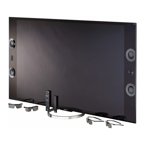
Sony XBR-65X900A Repair Manual
Lcd digital color tv rb1fs chassis
Hide thumbs
Also See for XBR-65X900A:
- Manual (211 pages) ,
- Operating instructions manual (40 pages) ,
- Features & specifications (5 pages)
Table of Contents
Advertisement
HISTORY INFORMATION FOR THE FOLLOWING MANUAL:
REPAIR MANUAL
XBR-65X900A
Version
Date
1.0
03/29/2013
2.0
07/03/2013
3.0
10/25/2013
4.0
12/20/2013
Subject
Original Manual Release Date.
Updated Section 3 - Repair Information. Reissue entire manual.
Updated Section 4 - Exploded View/Part Number Information. Replaced pages 22 - 28.
Updated Section 3 - Repair Information. Added pages 18 - 22.
Updated Section 4 - Exploded View/Part Number Information. Replaced pages 29 and 33.
RB1FS
MODEL
COMMANDER
XBR-65X900A
RM-YD087/RMF-YD001
Self Diagnosis
Supported model
Chassis
Segment: FS-M
DESTINATION
US/CND
LCD Digital Color TV
9-883-510-04
Advertisement
Table of Contents

Related Manuals for Sony XBR-65X900A


Summary of Contents for Sony XBR-65X900A
- Page 1 Self Diagnosis Supported model HISTORY INFORMATION FOR THE FOLLOWING MANUAL: REPAIR MANUAL RB1FS Chassis Segment: FS-M MODEL COMMANDER DESTINATION XBR-65X900A RM-YD087/RMF-YD001 US/CND XBR-65X900A Version Date Subject 03/29/2013 Original Manual Release Date. 07/03/2013 Updated Section 3 - Repair Information. Reissue entire manual.
-
Page 2: Table Of Contents
Overall Block Diagram / BAFS................6 Section 4 - Exploded View/Part Number Information .........27 Overall Block Diagram / BAF2S................7 Table-Top Stand ..................27 Power and Control Block Diagram.................8 XBR-65X900A .....................28 No Power Flowchart ....................9 Smart Core Block ..................31 Standby LED Blinking Flowchart .................10 Connectors ....................32 No Video Flowchart ..................... -
Page 3: Cautions And Warnings
Ne les remplacer que par des composants Sony dont le numero de piece est indique dans le present manuel ou dans des supplements publies par Sony. Les reglages NOTE: Do not modify the original design without obtaining written permission de circuit dont l’importance est critique pour la securite du fonctionnement... - Page 4 0.5 mA (500 microamperes). Leakage current can be measured by any one of three methods. A commercial leakage tester. Follow the manufacturers’ instructions provided with the tester. A battery-operated AC milliammeter. Figure B. Checking for earth ground. XBR-65X900A...
-
Page 5: Section 1 - Specifications And Layouts
SECTION 1 - SPECIFICATIONS AND LAYOUTS SPECIFICATIONS System Model name XBR-65X900A Television system NTSC: American TV standard Power and others ATSC (8VSB terrestrial): ATSC compliant 8VSB Power requirement USA/Canada 120 V AC, 60 Hz) QAM on cable: ANSI/SCTE 07 2000 (Does not include CableCARD functionality) -
Page 6: Board Layout
SECTION 1 - SPECIFICATIONS AND LAYOUTS BOARD LAYOUT XBR-65X900A TS BOARD POWER BOARD POWER BOARD (NETWORK) (NETWORK) POWER BOARD (E- LD) MAIN BOARD (BAFS/BAF2S) POWER POWER SUPPLY SUPPLY BOARD BOARD WLAN MODULE ASSEMBLY (G8) (G6) WLAN CX/CX2 BOARD* Module SWITCH UNIT... -
Page 7: Wire Dressing
SECTION 1 - SPECIFICATIONS AND LAYOUTS WIRE DRESSING XBR-65X900A SMART CORE BLOCK *CX/CX2 Board wire only included in models with BAFS Board (Serial No. 1800001 - 6010000). XBR-65X900A... -
Page 8: Section 2 - Troubleshooting
Total operation time by hour (MAX:65535) Total operation time by hour (MAX:65535) *Format of Error History = YYMMDDhhmmss example 120123132522= Jan 23, 2012 13:25:22 (1:25:22PM) NOTE: Date and time must be set for this to work. SAMPLE SELF CHECK DIAGNOSIS PAGE XBR-65X900A... -
Page 9: Triage Chart
* Immediate Shutdown After Power ON & 7X REFERENCE LIBRARY DATABASE FOR CORRECT REPLACEMENT PARTS BASED ON SERIAL NUMBER. To access the most recent version of the Triage documents for the models listed in this manual, login into the Sony Authorized Servicer Portal at http://www.sony.com/asp. XBR-65X900A... -
Page 10: Flowcharts And Diagrams
VIDEO SWITCH HDMI 2 PROCESS HDMI 3 HDMI 4 LVDS CX/CX2 TCON ETHERNET LVDS USB2.0 USB HUB LCD PANEL USB3.0 BAFS LED DRIVE SMART CORE SWITCH IR RX UNIT OPTICAL BLUETOOTH WIFI SENSE POWER SUPPLY POWER SUPPLY AC IN XBR-65X900A... -
Page 11: Overall Block Diagram / Baf2S
VIDEO SWITCH HDMI 2 PROCESS HDMI 3 HDMI HDMI 4 LVDS TCON ETHERNET LVDS USB HUB USB2.0 LCD PANEL USB3.0 BAF2S LED DRIVE SMART CORE SWITCH IR RX UNIT OPTICAL BLUETOOTH WIFI SENSE POWER SUPPLY AC IN POWER SUPPLY XBR-65X900A... -
Page 12: Power And Control Block Diagram
STANDBY POWER SUPPLY MAIN BOARD CN9101 CN6401 POWER_ON AC_OFF_DET POWER_ON TCON_ON AC_OFF_DET STBY3.3V TCON_ON TCON_12V STBY3.3V REG_12V STBY GND AU_GND 12~14 21~23 TCON_GND 18~20 DIGITAL_STBY TCON_12V BL_ON 12~17 REG_12V 6~11 BL_ERR BL_ON CN4803 BL_ERR REG_12V (AU) DIGITAL_STBY GND (AU) BAFS/BAF2S XBR-65X900A... -
Page 13: No Power Flowchart
See Stanby High (3.3V) Power Supply Is Standby LED Power Supply LED Blinking appears Board* blinking? Board* Flowchart momentarily? Power Supply Main Board* Board* *For Part Number information, refer to “Section 4 - Exploded View/Part Number Information” on page XBR-65X900A... -
Page 14: Standby Led Blinking Flowchart
Board* See Triage Chart HEM3 Board Main Board* After a while Check ventilation Immediately TCON* Power Supply Main Board* LCD Panel* (LCD Panel) Board* *For Part Number information, refer to “Section 4 - Exploded View/Part Number Information” on page XBR-65X900A... -
Page 15: No Video Flowchart
Locate Backlights CN6401 on Zero volts at Zero volts at LCD Panel* turned on? Power Supply Pin 5? Pin 3? Board. Sony logo TCON* Main Board* appears Main Board* (LCD Panel) momentarily? Unplug LVDS connector with Test patterns TCON* unit off. Turn unit... -
Page 16: Video Distorsion Flowchart
Main Board* (LCD Panel) Any horizontal LCD Panel* lines? Any single or LCD Panel* isolated vertical lines? More than 1 TCON* vertical band? (LCD Panel) *For Part Number information, refer to “Section 4 - Exploded View/Part Number Information” on page XBR-65X900A... -
Page 17: No 3D Viewing
“Simulated 3D”. Double images Main Board* displayed on screen? View image with Double images Passive 3D Passive 3D become one? Glasses Glasses. 3D OK *For Part Number information, refer to “Section 4 - Exploded View/Part Number Information” on page XBR-65X900A... -
Page 18: Section 3 - Repair Information
2. Grasp Cover Under as shown, then carefully pull upwards to release the locking clips and lift to detach. 4. Grasp Rear Cover as shown and lift to detach. 3. Remove 4 screws from Table-Top Stand and pull down as shown to detach from Rear Cover. XBR-65X900A... -
Page 19: Replacing The Main Board
Lift the black locking bar to reconnect the FFC Cable and secure the connector. 3. Slide Bracket Side and Bracket Under to remove from Main Board. 7. Reconnect remaining connectors. Side Bracket Side Bracket Under Bracket Under Bracket XBR-65X900A... - Page 20 13. Press then to save the changes. MUTING After ALL repairs UPDATE the SOFTWARE to the latest version. Instructions are included with the Software package on the Sony DIGITAL SERVICE website. 002 MODEL a. Insert the USB device with the latest Software into the TV.
- Page 21 Serial Number input screen and re-enter POWER the correct number. 24. Cycle AC Power (Unplug and plug AC Cord from the outlet). 22. Press to save the Serial Number. DIGITAL (MODEL) SERVICE SerialNumberEdit *1 SerialNumber 1800001 WRITE XBR-65X900A...
-
Page 22: Replacing The Power Supply Board
After ALL repairs UPDATE the SOFTWARE to the latest version. 3. Remove 6 screws from TCON Shield Case and lift as shown to remove Instructions are included with the Software package on the Sony from Rear Cover, then detach from the TCON Board. - Page 23 Channel Volume After ALL repairs UPDATE the SOFTWARE to the latest version. DISPLAY POWER Instructions are included with the Software package on the Sony website. until the VPC Menu appears. 12. Press OPTION a. Remove all signal connections from the TV.
- Page 24 Product ID AM0.510WW EFR:03.00.00.15 DNC:------------- MID:04835511 DNI:-------------- 18. Press until 001 BU_NVM item displays. PID:04020000 DNF:------------- PNL: T550QVD02.0 TGC:---__TGE:--- SCF:20.01 SERVICE SYF:-------------- PANEL BU_NVM NOTE: Use the following table for reference to verify the Model ID and Product ID. XBR-65X900A...
- Page 25 18586300 0F4D18B1 01062040 UD3Y650LN0101 FB_BASE ATSC-UC_BASE XBR-65X850A 18586301 0F4D18B1 01062040 UD3Y650LN0101 FB_BASE ATSC-UC_BASE XBR-65X850A 18586302 074D18B1 03062040 UD3Y650LN0101 FB_BASE ATSC-LTN_BASE XBR-65X900A 18521100 0F0D18A0 01060040 T650QVD01.0 FSM-FSL_BASE ATSC-UC_BASE XBR-65X900A 18559900 0F0D18A0 01060040 T650QVD01.0 FSM-FSL_BASE ATSC-UC_BASE XBR-65X900A 18559901 0F0D18A0 01060040 T650QVD01.0 FSM-FSL_BASE...
-
Page 26: Replacing The Cx Board
HDMI CAUTION: TV will turn ON and OFF during this process. FORCE_ARC until 002 RUN_EDID_SEQ item displays. 7. Press CHASSIS SERVICE HDMI RUN_EDID_SEQ f. After removing the USB device, press to turn TV OFF. POWER XBR-65X900A... - Page 27 13. Cycle AC Power (Unplug and plug AC Cord from the outlet). 14. When normal OSD (On Screen Display) graphics appear, wait 10 CHASSIS SERVICE seconds and cycle AC Power again. 15. TV turns ON with normal OSD. PID_DATA_MISMAT XBR-65X900A...
-
Page 28: Replacing The Switch Unit
2. Install the new Switch Unit, screws and connectors. Module Module REMOVING THE WOOFER SPEAKER 1. Disconnect connector from Woofer Speaker, remove 5 screws and lift to detach. 2. Refer to these instructions to remove the opposite Woofer Speaker. XBR-65X900A... -
Page 29: Removing The Side Speakers
3. Carefully disconnect all remaining connectors from PWB Board and lift to Speaker Speaker detach. Bracket Bracket Speaker Speaker Loud Speaker Loud Speaker Ornament Ornament (Passive Radiator) (Passive Radiator) 8. Refer to these instructions to remove the opposite Side Speakers. XBR-65X900A... -
Page 30: Removing The Smart Core Block
Lid, SC 4. Release the HSF Board connector from the locking clip to disconnect it and lift to detach. Then, disconnect and remove HSF Board, FPC-BT and Bluetooth Module. HSF Board HSF Board FPC-BT FPC-BT Bluetooth Bluetooth Module Module XBR-65X900A... -
Page 31: Section 4 - Exploded View/Part Number Information
Specific instructions must be adhered to whenever these components are mark are critical for safety. repaired and/or replaced. (See Appendix A) Replace only with part number specified. REF. NO. PART NO. DESCRIPTION 4-462-872-01 NECK, STAND ASSEMBLY 4-454-672-02 STAND XBR-65X900A... -
Page 32: Xbr-65X900A
NOTE: The components identified by a red outline and a mark contain confidential NOTE: The components identified by shading and XBR-65X900A information. Specific instructions must be adhered to whenever these components are mark are critical for safety. repaired and/or replaced. (See Appendix A) Replace only with part number specified. - Page 33 *1 Reinstall Bracket HUS when replacing the LCD Panel. ORDER THIS PART WHEN REPLACING THE LCD PANEL. *2 Reinstall TCON Shield Case when replacing the TCON Board. A-1936-365-A TS BOARD, MOUNTED 4-457-426-01 GASKET (BAF) ORDER THIS PART WHEN REPLACING THE LCD PANEL. XBR-65X900A...
- Page 34 ORDER THIS PART WHEN REPLACING THE LCD PANEL. 1-858-896-11 LOUD SPEAKER (PASSIVE RADIATOR) 4-454-660-01 COVER, WOOFER (LEFT) 1-858-895-11 SP BOX ASSEMBLY 4-454-661-01 COVER, WOOFER (RIGHT) 4-454-658-01 COVER, SP (RIGHT) ORDER THIS PART WHEN REPLACING THE LCD PANEL. Smart Core Block XBR-65X900A...
-
Page 35: Smart Core Block
Replace only with part number specified. REF. NO. PART NO. DESCRIPTION 4-463-080-01 LID, SC A-1936-360-A HIF BOARD, MOUNTED 1-846-688-11 FPC BT ORDER THIS PART WHEN REPLACING BLUETOOH MODULE OR HSF LM BOARD. A-1936-358-A HSF LM BOARD, MOUNTED 1-492-062-11 BLUETOOTH MODULE 4-454-668-01 CASE BARE, SC XBR-65X900A... -
Page 36: Connectors
FOR SERIAL No. 1800001 - 6610000 ONLY. 1-846-714-11 CONNECTOR ASSEMBLY 3P (G6-G8) 1-910-107-84 CONNECTOR ASSEMBLY 3P (BAF-TS) 1-910-107-81 HARNESS ASSEMBLY (G6/G8-LD) 1-910-107-82 (LVDS) FLEXIBLE FLAT CABLE 20P 1-910-107-74 CONNECTOR ASSEMBLY 5P 1-846-700-11 (LVDS) FLEXIBLE FLAT CABLE 51P 1-846-701-11 (LVDS) FLEXIBLE FLAT CABLE 41P XBR-65X900A... -
Page 37: Screws
(See Appendix A) Replace only with part number specified. DESCRIPTION XBR-65X900A Speaker Box Assembly Right (5), Speaker Box Assembly Left (5), 4-256-393-01 SCREW, +PSW M3X6 W12 AC Cover (1), Woofer Cover Right (1), Woofer Cover Left (1) -
Page 38: Section 5 - Accessories/Part Number Information
(SCREWS TO ATTACH TABLE-TOP STAND TO LCD TV) X-2586-996-1 PASSIVE 3D GLASSES For product protection and safety reasons, Sony strongly recommends that you use the screws provided with the TV. CAUTION: These screws cannot be used to secure the TV REMOTE COMMANDER to the Wall Mount Brackets. -
Page 39: Appendix A: Encryption Key Components
APPENDIX A: ENCRYPTION KEY COMPONENTS Encryption key components developed by Sony Corporation contain confidential information and shall be handled under the non-disclosure obligations provided in the applicable agreement with Sony Corporation (and/or its subsidiary). As part of this agreement specific instructions must be adhered to whenever a Circuit Board containing encryption key components is repaired and/or replaced pursuant to the following: In the service manual the Circuit Board(s) containing encryption key components shall be identified with a red outline and a .
Need help?
Do you have a question about the XBR-65X900A and is the answer not in the manual?
Questions and answers