
Subscribe to Our Youtube Channel
Related Manuals for HBM PW25P Series


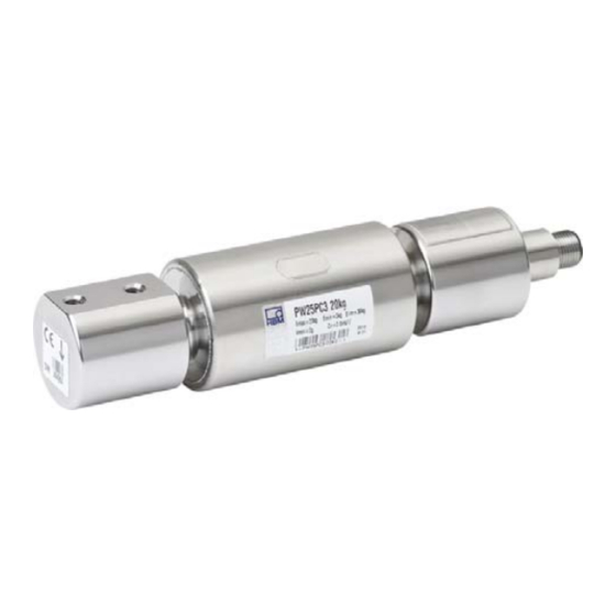
Summary of Contents for HBM PW25P Series
- Page 1 Mounting Instructions | Montageanleitung | Notice de montage English Deutsch Français PW25P...
- Page 2 Tel. +49 6151 803-0 Fax +49 6151 803-9100 info@hbm.com www.hbm.com Mat.: 7-0101.0006 DVS: A03627_02_Y00_01 HBM: public 08.2018 E Hottinger Baldwin Messtechnik GmbH. Subject to modifications. All product descriptions are for general information only. They are not to be understood as a guarantee of quality or durability.
- Page 3 Mounting Instructions | Montageanleitung | Notice de montage English Deutsch Français PW25P...
-
Page 4: Table Of Contents
..........PW25P A03627_02_Y00_01 HBM: public... -
Page 5: Safety Instructions
S Breaking loads S Temperature limits S Limits of electrical loading capacity Note, that when several load cells are installed in a scale, there is not always an even distribution of load on the individual load cells. PW25P A03627_02_Y00_01 HBM: public... - Page 6 Load cells can break, particularly in the case of overloading. The breakage of a load cell can also cause damage to property or injury to persons in the vicinity of the load cell. PW25P A03627_02_Y00_01 HBM: public...
- Page 7 If you need more information about disposal, please contact your local authorities or the dealer from whom you purchased the product. PW25P A03627_02_Y00_01 HBM: public...
- Page 8 3. As system startup engineers or service engineers, you have successfully completed the training to qualify you to repair the automation systems. You are also authorized to ground and label circuits and equipment and place them in operation in accordance with safety engineering standards. PW25P A03627_02_Y00_01 HBM: public...
-
Page 9: Markings Used
Symbols on the product CE mark The CE mark enables the manufacturer to guarantee that the product complies with the requirements of the rele vant EC directives (the declaration of conformity is avail able at http://www.hbm.com/HBMdoc). PW25P A03627_02_Y00_01 HBM: public... -
Page 10: Conditions On Site
Deposits Dust, dirt and other foreign matter must not be allowed to accumulate sufficiently to divert some of the measuring force onto the housing, thus invalidating the measured value (force shunt). PW25P A03627_02_Y00_01 HBM: public... -
Page 11: Mechanical Installation
S Welding currents must not be allowed to flow over the transducer. If there is a risk that this might happen, you must provide a suitable low‐ohm connection to electrically bypass the transducer. HBM provides the highly flexible EEK ground cable for this purpose, for example, that is screwed on above and below the transducer. - Page 12 10 Nm (customer construction) max. thread reach 10 mm Fig. 4.1 Load application and installation Important Load must not be applied to the side where the cable connection is located, as this would cause a force shunt. PW25P A03627_02_Y00_01 HBM: public...
-
Page 13: Electrical Connection
Marking (+) with (+) and marking (-) with (-), see Fig. 5.1. This measure also reduces the cable resistance of the PW25P A03627_02_Y00_01 HBM: public... -
Page 14: Shortening The Cable
The cable of a six‐wire transducer can be extended with a cable of the same type. Parallel connection Only load cells with an aligned output (nominal (rated) sensitivity and output resistance) are suitable for parallel connection. This option is not available with type PW25P load cells. PW25P A03627_02_Y00_01 HBM: public... -
Page 15: Emc Protection
EMC protection for the measuring chain. Electrical and magnetic fields often induce interference voltages in the measuring circuit. Therefore: S Use shielded, low‐capacitance measurement cables only (HBM cables fulfill both conditions). S Do not route the measurement cables parallel to power lines and control circuits. -
Page 16: Specifications
Specifications Specifications Information Further product information can be found at www.hbm.com/pw Dimensions Dimensions in mm (1 mm = 0.03937 inches) 1-KAB168 or 1-KAB175 1-KAB168: ∅D = 14.5; L = 62 1-KAB175: ∅D = 16; L = 62 6 19+0.1 100+0.2 Connector plug 19+0.1... -
Page 17: Accessories
Pin assignment 1-KAB168 Color code Connection White Measurement signal (+) Measurement signal (-) Blue Excitation voltage (+) Pink Excitation voltage (-) Green Sense lead (+) Gray Sense lead (-) Yellow Not in use Brown Not in use PW25P A03627_02_Y00_01 HBM: public... - Page 18 Accessories Pin assignment 1-KAB175 Color code Connection White Measurement signal (+) Measurement signal (-) Blue Excitation voltage (+) Black Excitation voltage (-) Green Sense lead (+) Gray Sense lead (-) PW25P A03627_02_Y00_01 HBM: public...
- Page 19 Mounting Instructions | Montageanleitung Notice de montage English Deutsch Français PW25P...
- Page 20 ..........PW25P A03627_02_Y00_01 HBM: public...
-
Page 21: Sicherheitshinweise
S Grenzlast bei max. Exzentrizität S Grenzquerbelastung S Bruchlasten S Temperaturgrenzen S Grenzen der elektrischen Belastbarkeit Beachten Sie, dass beim Einbau mehrerer Wägezellen in eine Waage die Last verteilung auf die einzelnen Wägezellen nicht immer gleichmäßig ist. PW25P A03627_02_Y00_01 HBM: public... - Page 22 Jede Person, die mit Aufstellung, Inbetriebnahme, Betrieb oder Repa ratur einer Wägezelle beauftragt ist, muss die Montageanleitung und insbeson dere die sicherheitstechnischen Hinweise gelesen und verstanden haben. Bei nicht bestimmungsgemäßem Gebrauch der Wägezellen, bei Nichtbeachtung der Montage‐ und Bedienungsanleitung, dieser Sicherheitshinweise oder sons PW25P A03627_02_Y00_01 HBM: public...
- Page 23 Der Aufnehmer darf ohne unsere ausdrückliche Zustimmung weder konstruktiv noch sicherheitstechnisch verändert werden. Jede Veränderung schließt eine Haftung unsererseits für daraus resultierende Schäden aus. Wartung Die Wägezellen PW25P… sind wartungsfrei. Veräußerung Bei einer Veräußerung der Wägezelle ist diese Montageanleitung der Wäge zelle beizulegen. PW25P A03627_02_Y00_01 HBM: public...
- Page 24 3. Sie sind Inbetriebnehmer oder für den Service eingesetzt und haben eine Ausbildung absolviert, die Sie zur Reparatur der Automatisierungsanlagen befähigt. Außerdem haben Sie eine Berechtigung, Stromkreise und Geräte gemäß den Normen der Sicherheitstechnik in Betrieb zu nehmen, zu erden und zu kennzeichnen. PW25P A03627_02_Y00_01 HBM: public...
-
Page 25: Verwendete Kennzeichnungen
Dokumente und Dateien. Auf dem Gerät angebrachte Symbole CE-Kennzeichnung Mit der CE‐Kennzeichnung garantiert der Hersteller, dass sein Produkt den Anforderungen der relevanten EG‐Richtlinien entspricht (die Konformitätserklärung finden Sie auf der Website von HBM (www.hbm.com) unter HBMdoc). PW25P A03627_02_Y00_01 HBM: public... -
Page 26: Bedingungen Am Einbauort
Die dadurch auftretende Korrosion kann zum Ausfall des Aufnehmers führen. Sehen Sie in diesem Fall entsprechende Schutzmaßnahmen vor. Ablagerungen Staub, Schmutz und andere Fremdkörper dürfen sich nicht so ansammeln, dass sie einen Teil der Messkraft auf das Gehäuse umleiten und dadurch den Messwert verfälschen (Kraftnebenschluss). PW25P A03627_02_Y00_01 HBM: public... -
Page 27: Mechanischer Einbau
S Es dürfen keine Schweißströme über den Aufnehmer fließen. Sollte diese Gefahr bestehen, so müssen Sie den Aufnehmer mit einer geeigneten niederohmigen Verbindung elektrisch überbrücken. Hierzu bietet z. B. HBM das hochflexible Erdungskabel EEK an, das oberhalb und unterhalb des Aufnehmers angeschraubt wird. - Page 28 Zwischenplatte Anzugsmoment (Konstruktion durch Kunden) 10 Nm max. Einschraub- tiefe 10 mm Abb. 4.1 Lasteinleitung und Einbau Wichtig Die Lasteinleitung darf nicht auf der Seite des Kabelanschlusses erfolgen, dies führt zu einem Kraftnebenschluss durch das Kabel. PW25P A03627_02_Y00_01 HBM: public...
-
Page 29: Elektrischer Anschluss
Vierleiter‐Technik anschließen, müssen Sie die Fühlerleitungen der Aufnehmer mit den entsprechenden Speisespannungsleitungen verbinden: Kennzeichnung (+) mit (+) und Kennzeichnung (-) mit (-), siehe Abb. 5.1. Diese Maßnahme verkleinert unter anderem den Kabelwiderstand der Speise PW25P A03627_02_Y00_01 HBM: public... -
Page 30: Kabelkürzung
Das Kabel eines Sechsleiter‐Aufnehmers kann mit einem gleichartigen Kabel verlängert werden. Parallelschaltung Nur Wägezellen mit abgeglichenem Ausgang (Nennkennwert und Ausgangswi derstand) sind zur Parallelschaltung geeignet. Diese Option ist bei den Wäge zellen vom Typ PW25P nicht lieferbar. PW25P A03627_02_Y00_01 HBM: public... -
Page 31: Emv-Schutz
EMV‐Schutz der Messkette zu erreichen. Elektrische und magnetische Felder verursachen oft eine Einkopplung von Störspannungen in den Messkreis. Deshalb: S Verwenden Sie nur abgeschirmte, kapazitätsarme Messkabel (HBM‐Kabel erfüllen diese Bedingungen). S Legen Sie die Messkabel nicht parallel zu Starkstrom‐ und Steuerleitungen. -
Page 32: Technische Daten
Technische Daten Technische Daten Information Weitere Produktinformationen unter www.hbm.com/de/pw Abmessungen Abmessungen in mm 1−KAB168: ∅D = 14,5; L = 62 1−KAB175: ∅D = 16; L = 62 1−KAB168 oder 1−KAB175 6 19±0,1 100±0,2 Anschlussstecker Anschluss- 19±0,1 stecker 15,5 150±0,2 25,5... -
Page 33: Zubehör
IP68/IP69K, Hygieneausführung 6 m lang Technische Daten der Anschlusskabel siehe separates Datenblatt B3643. Anschlussbelegung 1-KAB168 Aderfarbe Anschluss Weiß Messsignal (+) Messsignal (-) Blau Speisespannung (+) Rosa Speisespannung (-) Grün Fühlerleitung (+) Grau Fühlerleitung (-) Gelb Nicht belegt Braun Nicht belegt PW25P A03627_02_Y00_01 HBM: public... - Page 34 Zubehör Anschlussbelegung 1-KAB175 Aderfarbe Anschluss Weiß Messsignal (+) Messsignal (-) Blau Speisespannung (+) Schwarz Speisespannung (-) Grün Fühlerleitung (+) Grau Fühlerleitung (-) PW25P A03627_02_Y00_01 HBM: public...
- Page 35 Mounting Instructions | Montageanleitung | Notice de montage English Deutsch Français PW25P...
- Page 36 ..........PW25P A03627_02_Y00_01 HBM: public...
-
Page 37: Consignes De Sécurité
S les limites de température, S les limites de charge électrique. En cas de montage de plusieurs pesons dans une balance, notez que la charge n'est pas toujours répartie de façon homogène sur les différents pesons. PW25P A03627_02_Y00_01 HBM: public... - Page 38 à la sécurité. En cas PW25P A03627_02_Y00_01 HBM: public...
- Page 39 Nous ne saurions en aucun cas être tenus responsables des dommages qui résulteraient d'une modification quelconque. Entretien Les pesons PW25P… sont sans entretien. Cession En cas de cession du peson, la présente notice de montage doit être jointe au peson. PW25P A03627_02_Y00_01 HBM: public...
- Page 40 à réparer les installations d'automatisation. Vous êtes en outre autorisé à mettre en service, mettre à la terre et marquer des circuits électriques et appareils conformément aux normes de la technique de sécurité. PW25P A03627_02_Y00_01 HBM: public...
-
Page 41: Marquages Utilisés
Marquages utilisés sur le produit Label CE Avec le marquage CE, le fabricant garantit que son pro duit est conforme aux exigences des directives CE qui s'y appliquent (Pour voir la déclaration de conformité visitez http://www.hbm.com/HBMdoc). PW25P A03627_02_Y00_01 HBM: public... -
Page 42: Conditions Environnantes À Respecter
Dépôts La poussière, la saleté et autres corps étrangers ne doivent pas s'accumuler sous peine de dévier une partie de la force de mesure sur le boîtier et ainsi de fausser la valeur de mesure (shunt). PW25P A03627_02_Y00_01 HBM: public... -
Page 43: Montage Mécanique
S Aucun courant de soudage ne doit traverser le capteur. Si cela risque de se produire, le capteur doit être shunté électriquement à l'aide d'une liaison de basse impédance appropriée. À cet effet, HBM propose par ex. le câble de mise à terre très souple EEK vissé au‐dessus et au‐dessous du capteur. - Page 44 Longueur de filet maxi. 10 mm Fig. 4.1 Application de charge et montage Important La charge ne doit pas être appliquée du côté du raccordement du câble afin d'éviter tout shunt de force dû au câble. PW25P A03627_02_Y00_01 HBM: public...
-
Page 45: Raccordement Électrique
: (+) avec (+) et (-) avec (-), voir Fig. 5.1. Cette mesure réduit entre autres la résistance PW25P A03627_02_Y00_01 HBM: public... -
Page 46: Raccourcissement De Câble
Le câble d'un capteur à six fils peut être rallongé avec un câble de même type. Branchement en parallèle Seuls les pesons avec sortie ajustée (sensibilité nominale et résistance de sortie) sont adaptés pour un branchement en parallèle. Cette option n'est pas disponible pour les pesons de type PW25P. PW25P A03627_02_Y00_01 HBM: public... -
Page 47: Protection Cem
C'est pourquoi il faut : S utiliser uniquement des câbles de mesure blindés de faible capacité (les câbles HBM satisfont à ces conditions). S absolument éviter de poser les câbles de mesure en parallèle avec des lignes de puissance et de contrôle. -
Page 48: Caractéristiques Techniques
Caractéristiques techniques Caractéristiques techniques Information Pour plus d'informations sur les produits, voir www.hbm.com/fr/pw Dimensions Dimensions en mm 1-KAB168 oder 1-KAB175 1-KAB168 : ∅D = 14,5 ; L = 62 1-KAB175 : ∅D = 16 ; L = 62 6 19+0,1... -
Page 49: Accessoires
Couleur du fil Raccordement Blanc Signal de mesure (+) Rouge Signal de mesure (-) Bleu Tension d'alimentation (+) Rose Tension d'alimentation (-) Vert Fil de contre‐réaction (+) Gris Fil de contre‐réaction (-) Jaune Libre Marron Libre PW25P A03627_02_Y00_01 HBM: public... - Page 50 Code de raccordement 1-KAB175 Couleur du fil Raccordement Blanc Signal de mesure (+) Rouge Signal de mesure (-) Bleu Tension d'alimentation (+) Noir Tension d'alimentation (-) Vert Fil de contre‐réaction (+) Gris Fil de contre‐réaction (-) PW25P A03627_02_Y00_01 HBM: public...
- Page 51 Accessoires PW25P A03627_02_Y00_01 HBM: public...
- Page 52 HBM Test and Measurement Tel. +49 6151 803-0 Fax +49 6151 803-9100 info@hbm.com measure and predict with confidence...
Need help?
Do you have a question about the PW25P Series and is the answer not in the manual?
Questions and answers