Table of Contents
Advertisement
Quick Links
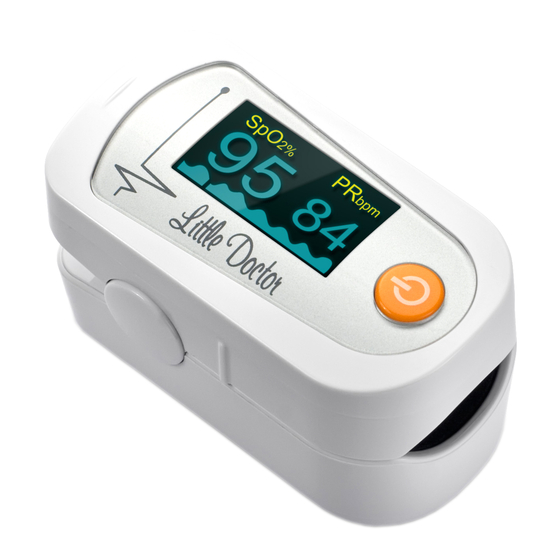
INSTRUCTION MANUAL
Fingertip Pulse Oximeter
model MD300C23
GENERAL DESCRIPTION
Oxygen Saturation is a percentage of Oxyhemoglobin (HbO
compounded with oxygen, by all combinative hemoglobin (Hb) capacity in
blood. In other words, it is consistency of Oxyhemoglobin in blood. It is a very
important parameter for the Respiratory circulation System.
Many respiratory diseases can result in oxygen saturation being lowered in
human blood. Additionally, the following factors can reduce oxygen saturation:
Automatic regulation of organ dysfunction caused by Anesthesia, Intensive
Postoperative Trauma, injuries caused by some medical examinations.
That situation might result in light-headedness, asthenia, and vomiting.
Therefore, it is very important to know the oxygen saturation of a patient so
that doctors can fi nd problems in a timely manner.
PARTS LIST
fi g. 1
MEASUREMENT PRINCIPLE
Principle of the Oximeter is as follows: A mathematical formula is established
making use of Lambert Beer Law according to Spectrum Absorption
Characteristics of Reductive hemoglobin (RHb) and Oxyhemoglobin (HbO
in glow and near-infrared zones.
Operation principle of the instrument is Photoelectric Oxyhemoglobin
Inspection Technology is adopted in accordance with Capacity Pulse Scanning
and Recording Technology, so that two beams of diff erent wavelength of
lights (660nm glow and 940nm near infrared light) can be focused onto a
human nail tip through a clamping fi nger-type sensor.
A measured signal obtained by a photosensitive element, will be shown
on OLED display through process in electronic circuits and microprocessor
shown on OLED display through electronic circuits and a microprocessor.
Diagram of Operation Principle
1. 1.Red and Infrared-ray Receipt Tube.
2. 1.Red and Infrared-ray Emission Tube. (fi g.2)
PRECAUTIONS FOR USE
1. Do not use the pulse oximeter in an MRI or CT environment.
2. Do not use the pulse oximeter in situations where alarms are required.
3. Explosion hazard: Do not use the pulse oximeter in an explosive
atmosphere.
4. The pulse oximeter is intended only as an adjunct in patient assessment.
It must be used in conjunction with other methods of assessing clinical signs
and symptoms.
5. Check the pulse oximeter sensor application site frequently to determine
the positioning of the sensor and circulation and skin sensitivity of the patient.
6. Do not stretch the adhesive tape while applying the pulse oximeter
sensor. This may cause inaccurate readings or skin blisters.
7. Before use, carefully read the Instruction manual.
8. The pulse oximeter has no SpO
monitoring, as indicated by the symbol.
9. Prolonged use or the patient's condition may require changing the sensor
site periodically. Change sensor site and check skin integrity, circulatory
status, and correct alignment at least every 4 hours.
10. Inaccurate measurements may be caused by:
- autoclaving, ethylene oxide sterilizing, or immersing the sensors in
liquid may cause inaccurate readings.
- signifi cant levels of dysfunctional hemoglobins (such as carbonxy-
hemoglobin or methemoglobin)
- intravascular dyes such as indocyanine green or methylene blue
- high ambient light. Shield the sensor area (with a surgical towel, or
direct sunlight, for example) if necessary.
- excessive patient movement
- high-frequency electrosurgical interference
- venous pulsations
- placement of a sensor on an extremity with a blood pressure cuff ,
arterial catheter, or intravascular line.
- hypotension, severe vasoconstriction, severe anemia, or hypothermia
- fi ngernail polish or false fi ngernails may cause inaccurate SpO
readings.
- the patient is in cardiac arrest or is in shock.
11. The pulse oximeter can be used before or after sports. Operation in sport
procedure is not recommended)
12. Please follow the law of the local government to deal with used battery.
Complete set: Main Unit – 1 pcs.,
Instruction Manual with Warranty
Card – 1 pcs., Hang Lace – 1 pcs.,
batteries – 2 pcs. (fi g. 1)
1
2
fi g. 2
alarms; it is not for continuous
2
BATTERY INSTALLATION
1. Shift the
bottom
panel and
then open it
) capacity,
(fi g.3a).
2
2. Put the two
AAA batteries
into battery cassette in correct polarities (fi g. 3b).
2. Close the bottom panel (fi g. 3c).
WARNING!
Replace batteries when low power indncator "
Power button
Please remove the battery if the Oximeter will not be used for a long time.
Do not use re-chargable batteries.
HOW TO USE
WARNING! Do not tremble the hand with oximeter during measuremrnt
1. Open the clamp (fi g. 4)
2. Plug one of fi ngers into rubber
hole of the oximeter (it is best to
plug the fi nger thoroughly) before
releasing the clamp.
3. Press the button
panel.
Display modes.
After turning on the oximeter, each time you press the power switch, the
oximeter will switch to another display mode, there are 6 display modes
)
shown as follows:
2
SpO
2%
95
1
4
4. Read correspondent data from display screen:
Low power indicator
Brightness adjustment
When you press the power switch for a long time (more than one second),
the brightness of the oximeter will be changed by degrees, there are 10 levels
on brightness; the default level is level four.
HANG LACE INSTALLATION
1. Thread thinner end of the hang lace through
the hanging hole (fi g. 5).
2. Thread thicker and of the lace through the
threaded end before pulling it tightly.
MAINTENANCE AND STORAGE
1.
Replace the batteries timely when low voltage lamp is lighted
2.
Clean surface of the fi ngertip oximeter before it is used in diagnosis for
patients
3.
Remove the batteries inside the battery cassette if the Oximeter will not
be operated for a long time.
4.
It is best to preserve the product in a place where ambient temperatures
-20-55r and humidity is <93%.
5.
It is recommended that the product should be kept in a dry environment
anytime. A wet ambient might aff ect its lifetime and even might damage
the product.
6.
Please follow the law of the local govern ment to deal with used battery
SPECIFICATION
Model
Display
SpO
2
measurement range
accuracy
Pulse Rate
measurement range
2
accuracy
Measurement wavelengths
red
infrared
fi g. 3a
fi g. 3b
there is no indication on display.
once on front
PR
PR
SpO
bpm
2%
bpm
97
84
74
2
PR
SpO
bpm
2%
5
PR
SpO
bpm
2%
97
74
PR signal
intensity Bar
graph
Pulse Wave
MD300C23
OLED display
70% - 100%
±2%
30 - 250 bpm
30 - 99 bpm - ±2 bpm;
100 - 250 bpm - ±2%
660 nm
905 nm
fi g. 3c
" is lit or if after pressing
fi g. 4
PR
SpO
2%
bpm
98
77
3
6
SpO
PR
bpm
2%
95
84
SpO
PR
2
fi g. 5
Advertisement
Table of Contents

Related Manuals for Little Doctor MD300C23


Summary of Contents for Little Doctor MD300C23
- Page 1 INSTRUCTION MANUAL BATTERY INSTALLATION Fingertip Pulse Oximeter 1. Shift the model MD300C23 bottom panel and GENERAL DESCRIPTION then open it Oxygen Saturation is a percentage of Oxyhemoglobin (HbO ) capacity, (fi g.3a). compounded with oxygen, by all combinative hemoglobin (Hb) capacity in 2.
- Page 2 Retailer sign Retailer stamp I confi rm that surface appearance and complete set of device is OK: Purchaser sign ® Registered trade marks of Little Doctor International (S) Pte. Ltd. E416/1904/2 © Little Doctor International (S) Pte. Ltd., 2019...
Need help?
Do you have a question about the MD300C23 and is the answer not in the manual?
Questions and answers