Table of Contents
Advertisement
Quick Links
This manual is provided FREE OF CHARGE from
the "BoatAnchor Manual Archive" as a service to
the Boatanchor community.
It was uploaded by someone who wanted to help
you repair and maintain your equipment.
If you paid anyone other than BAMA for this manual,
you paid someone who is making a profit from the
free labor of others without asking their permission.
You may pass on copies of this manual to anyone
who needs it. But do it without charge.
Thousands of files are available without charge
from BAMA. Visit us at http://bama.sbc.edu
K4XL's
KAMA
- f '
Advertisement
Chapters
Table of Contents

Related Manuals for Tektronix 503


Summary of Contents for Tektronix 503
- Page 1 K4XL's KAMA - f ' This manual is provided FREE OF CHARGE from the “BoatAnchor Manual Archive” as a service to the Boatanchor community. It was uploaded by someone who wanted to help you repair and maintain your equipment. If you paid anyone other than BAMA for this manual, you paid someone who is making a profit from the free labor of others without asking their permission.
- Page 2 I V l / \ r s l U A L Serial Number Tektronix, Inc S.W. M illik a n W a y • P. O. Box 500 • Beaverton, Oregon 97005 • Phone 644-0161 • Cables: Tektronix 0 70-0 218-01...
- Page 3 WARRANTY A ll Tektronix instruments are w arranted against defective m aterials and w orkm an ship for one year. Tektronix transformers, manufactured in our own plant, are w a r ranted for the life of the instrument. Any questions w ith respect to the w a r...
- Page 4 IEEE Stand ard 260 “ Standard Symbols for U nits", MIL- STD-12B and other standards of the electronics industry. Change inform ation, if any, is located at the rear of this manual. Q /G3 © Type 503...
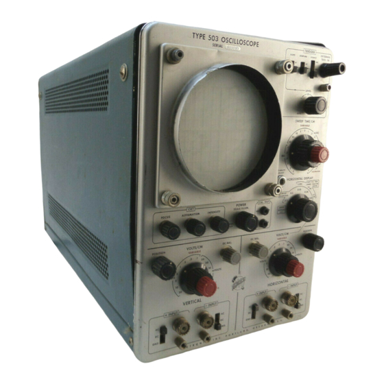
- Page 5 Fig. 1-1. Type 50 3 Oscilloscope. Type 503 ©...
- Page 6 SECTION 1 CHARACTERISTICS fiers may be operated with single-ended inputs for con Introduction ventional operation, or with differential inputs for can The Tektronix Type 503 Oscilloscope is a low-frequency, cellation of common-mode signals. Sweep rates to 1 micro high-sensitivity laboratory instrument...
- Page 7 Characteristics— Type 503 CALIBRATOR S upplem ental Inform ation Performance Requirement C haracteristic Amplitude Accuracy within ± 3 % 500 mV 5 mV Accuracy within ± 3 % 350 Hz ± 5 0 % Repetition Rate 30 to 70% Duty Cycle...
- Page 8 105 volts and 125 volts when the line transformer is wired The front panel of the Type 503 is shown in Fig. 2-2. for 117-volt operation, and between 210 volts and 250 volts Functions of all front panel controls and connectors are when the line transformer is wired for 234-volt operation.
- Page 9 000270 and above). PRELIMINARY INSTRUCTIONS INTENSITY Controls the brightness of the trace or To set up the Type 503 Oscilloscope for operation, pro spot on the screen. ceed as follows: POWER AND Turns instrument power on and off, and 1.
- Page 10 O p e ra tin g Instructions— Type 50 3 Fig. 2 -2 . Type 50 3 Oscilloscope fro n t panel. ©...
- Page 11 The graticule of the Type 503 Oscilloscope can be illu play of the voltages at the two ends of a resistor w ill show minated so that it appears to have either red or white the changes in current through the resistor.
- Page 12 CRT, and the input signal is applied through the vertical amplifier to the vertical deflection plates. The Type 503 allows selection, with the SWEEP TIME/CM control, of any one of 21 calibrated sweep rates, ranging in steps from 1 microsecond to 5 seconds per centimeter.
- Page 13 Setting the LEVEL control fully counterclockwise to the some external signal. This is especially true when the input AUTO, position sets the Type 503 Oscilloscope up for an waveform is of such small magnitude that it cannot provide automatic mode of triggering which is suitable for most stable triggering of the sweep by itself.
- Page 14 Operating Instructions— Type 503 SLOPE Typical waveforms obtained with the LEVEL control set in the — region. SLOPE SLOPE Typical waveforms obtained with the LEVEL control set in the + region. When the LEVEL control is in the + region, the sweep is triggered on the upper portion of the waveform;...
- Page 15 1. Set the oscilloscsope up for conventional operation shift with the Type 503 Oscilloscope. No attempt has been with the signal applied to either of the vertical INPUT con made to describe any but the most basic techniques. Famili...
- Page 16 6. Divide the measurement obtained in step 4 by the measurement obtained in step 5 and multiply the result by width on the order of 100 MHz with the Type 503. How ever, limitations of the sweep magnifier at the faster sweep 360°.
- Page 17 Section 6 under Adjust Attenuator Compensation. USE OF PROBES Use of an attenuator probe with the Type 503 will reduce the capacitive and resistive loading on a circuit under test, but at the same time will also reduce the oscilloscope sen...
- Page 18 Type 503 SECTION 3 CIRCUIT DESCRIPTION NOTE Introduction This section manual contains detailed circuit A t Instrument Serial N um ber 6997, each h a lf o f description and analysis. To follow the theory o f circuit the d u a l-trio d e in p u t stage was replaced by a...
- Page 19 V24B is inverted, and appears as a negative-going signal at the input of the Trigger M ultivi W ith the Type 503 set for X-Y operation (HORIZONTAL brator. DISPLAY) switch in the HORIZ. AMPLIFIER (SWEEP DIS...
- Page 20 Circuit Description— Type 503 In this new state, V45B grid is more positive than V45A is in AUTO, feedback is added to the circuit converting it grid. C31 will change its charge and move V45A grid to to a free-running 50-Hz multivibrator. In the AUTO mode, ward the new more positive level on V45B grid.
- Page 21 V135A positive enough to keep V135A in conduction until after the Miller Runup Circuit The CRT in the Type 503 oscilloscope makes use of an has stabilized in the quiescent condition. extra set of deflection plates for unblanking during sweep Under quiescent conditions, normal conduction through time.
- Page 22 Circuit Description— Type 503 CALIBRATOR POWER SUPPLY T601 provides filament power for the graticule lights, The calibrator provides a 500-millivolt square wave and all of the tubes, except the first stage of the Input Amplifier, a 5-millivolt square wave for use in calibrating the gain of and B + voltage (about 500 volts) for the power supply the Horizontal and Vertical Amplifiers.
- Page 23 NOTES...
- Page 24 In addition to the standard electronic tenance or troubleshooting of the Type 503. components, some speciol parts are used in the Type 503. These parts are manufactured or selected by Tektronix, Inc. to meet specific performance requirements, or are manu...
- Page 25 To remove the calhode-ray tube, first disconnect the Each checked pair of nuvistors used in the Type 503 tube socket and all leads connected to the neck of the tube. Vertical and Horizontal Amplifiers' is mounted in a temper...
- Page 26 Table 4-1 lists of ordinary tin-lead solder, or by the application of loo the main circuits in tho Type 503 and the series of circuit much heat. However, occasional use of ordinary solder w ill numbers assigned to each.
- Page 27 Type 503 power supply test points. The remainder of the can be made isolate the faulty circuit or circuits. In some wiring in the Type 503 is color-coded with two or less stripes, cases simple front panel checks can determine...
- Page 28 HORIZONTAL POSITION control, the nonlinearity Proper operation of every circuit in the Type 503 Oscillo is probably in the Sweep Generator. If the spacing between scope depends on proper operation o f the Power Supply.
- Page 29 Maintenance— Type 503 winding of T601 and the voltage doubler circuit if the volt age is not correct. A reading o f approxim ately 600 volts or more at the junction o f D612 and C612 indicates the oscil lator circuit [V620, T620) is inoperative or the line voltage is too high.
- Page 30 Maintenance— Type 503 If there is excessive ripple on only one of the supplies, first be checked. Then check for components which can check for open or leaky capacitors in that circuit. affect the gain of the circuit but not the DC balance. Such...
- Page 31 Maintenance— Type 503 divider network between the plate of V45A and the grid of check the adjustment of C406 and C416 and the high fre V45B is particularly critical. quency compensation networks in the attenuators. Refer to the Calibration section of this manual.
- Page 32 Maintenance— Type 503 If the voltage at the cathode of V145B, pin 3, is more not remain constant. If the nonlinearity exists at all sweep negative than —55 volts, check the tubes in the Hold-O ff rates, a defective M iller tube (V160A) is the probable cause Circuit, the H old-O ff capacitor, and resistors in the cathode of the trouble.
- Page 33 NOTES...
- Page 34 This section of the manual provides a means of rapidly 13. Adapter, male BNC and female UHF. Tektronix Part checking the performance of the Type 503. It is intended No. 103-0032-00. to check the calibration of the instrument without the need for performaing the complete Calibration Procedure.
- Page 35 Check— No horizontal shift of the spot as the SENSI 4. Allow the Type 503 to warm up for at least 5 minutes TIVITY switch is rotated from 1 mV/CM to .2 VOLTS/CM.
- Page 36 Performance Check— Type 503 g. Check— The display amplitude should be 5 cm ± c. Check— The dot spacing should be < 2 cm, indicating 1.5 mm. a ratio of >2.5:1. d. Return the VARIABLE control to the CALIBRATED posi...
- Page 37 Performance Check— Type 503 1 4 . Check A m p lifie r B a la n c e — V e rtic a l (DC C om m on M o d e Rejection) a. Requirement— Rejection ratios deflection toler...
- Page 38 AMPLIFIER (SWEEP DISABLED), and adjust the INTENSITY rounding, overshoot, or tilt. as desired. b. Set the Type 503 controls as follows: e. Repeat step 15(e), using the HORIZONTAL SENSITIV TRIGGER ITY switches. The display w ill be 2 dots.
- Page 39 Adjust the generator output for a display 3 cm in 2% overshoot, rounding, or tilt. amplitude, and center the display in the graticule viewing area. b. Set the Type 503 controls as follows: Rotate the LEVEL control counterclockwise to obtain a TRIGGER stable display (near 0).
- Page 40 R e q u i r e m i n W h a n shift no t m o re th an 1 ° to 4 5 obtain a stable display on the Type 503. The display should be similar to Fig. 5-4.
- Page 41 12 of Recommended Equipment) VOLTS/CM, using steps (e) through (k) as a guide, and refer may be installed at the Type 503 input ends of the cables, ring to Table 5-3 for attenuator settings, generator fre to permit easy cable-switching.
- Page 42 Performance Check— Type 503 Check Common Mode Rejection Ratio (AC) a. Requirement— Maximum display amplitudes as indi cated in Table 5-4, with specified signal inputs and deflec tion sensitivities. b. Set the HORIZONTAL + and — INPUT switches to GND.
- Page 43 -IN P U T greater than 4.2 cm (—3 dB). SWEEP TIME/CM 5 /iSEC h. Repeat the frequency response check for all positions Test Oscilloscope (Type 503) of the VERTICAL + and — INPUT attenuator (SENSITIVITY) switch. Vertical Sensitivity 10 mV/cm...
- Page 44 Requirement— Stable display in + and —SLOPE switch d. Connect one cable to the Type 503 VERTICAL + INPUT positions, and in AUTO, triggering. connector, and the other cable to the EXT. TRIG. IN con...
- Page 45 Requirement— Sweep accuracy ± 3 % (2.4 mm in 8 cm) +INPUT in all SWEEP TIME/CM ranges. -IN P U T b. Set the time-mark generator and Type 503 as indicated SWEEP TIME/CM 1 mSEC in Table 5-5, checking for timing accuracy tolerances as shown.
- Page 46 VERTICAL — INPUT connector. The display .h i mm/2 cm X 20 1 small mark/2 cm will be the difference between the Standard Calibrator volt ih2.5 mm/5 cm X 50 1 small mark/5 cm age and the Type 503 CALIBRATOR voltage. 5-13 ©...
- Page 47 Performance Check— Type 503 Check—The calibrator waveform symmetry should be f. Check— Trace separation at the vertical center of the display should not exceed 1.5 mm (3%). within a ratio of 2:1. g. Change the VERTICAL SENSITIVITY switch to .1 VOLTS/ 43.
- Page 48 SECTION 6 CALIBRATION 1. Test Oscilloscope. Minimum vertical deflection factor, Introduction 1 m V/div; bandwidth, DC to 450 kHz. Tektronix Type 503 The Type 503 Oscilloscope is a stable instrument and recommended. should not require frequent calibration. However, it will 2.
- Page 49 Type 503 ©...
- Page 50 <M) (161 tig . 6-2. H»tomm»nd»d equipm ent to r ca lib ra tio n o f tho Typo 503 O tc lllo tc o p o 20. 6-inch jumper lead with miniature allig a to r clip ter □...
-
Page 51: Table Of Contents
Calibration— Type 503 Horizontal/Vertical rejection ratio 100:1 with sensi f~1 14. Adjust Coarse DC Balance— Vertical. Page 6-10 tivities and signals specified. DC balancing by adjustment of R436. □ Check Vertical Amplifier Frequency Response. □ 15. Adjust Coarse DC Balance— Horizontal. -
Page 52: Calibration- Type 503
If only a partial calibration is performed, start with the near 4. Allow the Type 503 to warm up for at least 5 minutes est setup preceding the desired portion. - Page 53 Counterclockwise (but LEVEL ment) to the appropriate scale, and connect the leads to not AUTO) the Type 503 chassis ground and tho — 100 volt test point 1 mSEC SWEEP TIME/CM (see Fig. 6 4 for test point locations). VARIABLE CALIBRATED c.
- Page 54 C a lib ra tio n — Type 503 2. Check + 1 2 .6 Volt Supply NOTE Do not adjust the — 100 ADJ. co n tro l unless one a. Remove the meter lead from the — 100 volt test point or more o f the supply voltag es are out o f to le r...
- Page 55 Check Power Supply Ripple and Regulation TABLE 6-1 a. Test equipment setup is shown in Fig. 6-6. The Type Power 503 control settings remain as in Stop 1. Supply V o lta g e Ripple V o lta g e b.
- Page 56 50-ohm cable from the marker output to the Type 503 than 0 0 0 2 7 0 , the ASTIGMATISM control is located on the fro n t VERTICAL +IN P U T connector.
-
Page 57: F~1 14. Adjust Coarse Dc Balance- Vertical
C a lib ra tio n — Type 503 e. Position the trace to the center horizontal line with c. Adjust the VERTICAL SENSITIVITY switch and VARI tbe Vertical POSITION control. ABLE control so that the markers fill the vertical graticule area, and turn the TRIGGER LEVEL fully counterclockwise f. -
Page 58: Adjust .2 V /C M Gain- Vertical
BNC to UHF adapter, a 50 D cable and quick- -IN P U T G ND connect adopter (item 15 of Recommended Equipment) to the- Type 503 VERTICAL - f INPUT connector, and change POSITION Centered the VERTICAL + INPUT switch to DC. -
Page 59: I | 17. Check Variable Control Ratio- Vertical
Calibration— Type 503 d. Set the Standard Amplitude C alibrator to supply a 1-volt square wave, and connect the signal to the HORI ZONTAL - f INPUT connector. e. Set the HORIZONTAL SENSITIVITY switch to .2 VOLTS/ f. The display should now consist of two dots spaced horizontally in the graticule area. -
Page 60: 22. Check Compression Or Expansion- Horizontal
Calibration— Type 503 24. Check Compression or Expansion— Vertical 22. Check Compression or Expansion— Horizontal a. Set the Standard Amplitude Calibrator to .5 volts, and chanqe the HORIZONTAL + and — INPUT switches to a. Check that the SENSITIVITY switch is set to .2 VOLTS/ GND. -
Page 61: Check Attenuator Accuracy- Vertical + Input And - Input
Calibration— Type 503 e. Change the HORIZONTAL +INPU T switch to GND, and change the HORIZONTAL — INPUT switch to DC. Repeat step 26 (d) using the HORIZONTAL SENSI TIVITY switches. The display w ill be 2 dots. g. Remove the Standard Amplitude Calibrator signal. -
Page 62: Adjust Attenuator Compensation- Vertical. Page 6
C a lib ra tio n — Type 503 tig . 6 -1 S. Equipment i* t u p (o r a d |u itln g Vortical A m p llflo r a lU n u a to r com ponia tlon. - Page 63 Calibration— Type 5 0 3 C415C misadjusted (A ) C415C correctly adjusted Fig. 6 - 1 6 . T y p ic a l d is p la y s . V e rtic a l A m p lifie r a tte n u a to r c o m p e n s a tio n a d ju s tm e n ts ; 1 kH z s q u a re -w a v e in p u t; sw ee p sp ee d , 2 m illis e c o n d s / h.
- Page 64 C a lib ra tio n — Type 503 s. Check— Square front corner on waveform, with over Repeat the procedure outlined in steps (d) through (u), referring to Table 6-3 for control settling adjustments re shoot or rounding not exceeding 2% of display amplitude.
-
Page 65: Adjust Attenuator Compensation-Horizontal
Calibration— Type 503 Fig. 6 -1 9 . T a il sotup for H o rlio n la l A m p lifie r attenua tor com pensation adjustments. Conned a I-kHz square-wave signal from the square- Control Setting*: wave generator through a 50-ohm termination, a 50-ohm... - Page 66 C a lib ra tio n — Type 50 3 e. Connect a 50-ohm cable from the UHF T connector p. Change the HORIZONTAL SENSITIVITY switch to 5 to the EXTERNAL TRIG. IN connector. VOLTS/CM. q. Change the SWEEP TIME/CM to 2 mSEC, and adjust Rotate the LEVEL control to a point near 0 to obtain the display for a horizontal deflection of 3 cm.
- Page 67 Calibration— Type 503 C305C correctly o djusted (A ) C305C misadji J S t e d Fig. 6-23. H orizontal A m p lifie r attenua tor com pensation; 1 kHz square-wave input; SWEEP TIM E /C M switch setting, .1 mSEC.
-
Page 68: Adjust Amplifier Phasing
C a lib ra tio n — Type 503 fig . 6 -2 4 . T o tl setup lo r ad ju stin g a m p lifie r phasing Control Settings: f— SLOPE COUPLING INT. SOURCE FREE RUN... - Page 69 50-ohm cables to the output connector o f the constant- amplitude signal generator. If desired, tw o quick-connect adapters (item 15 o f Recommended Equipment) may be installed at the Type 503 input ends of the cables, to per mit easy cable-switching, NOTE The tw o 50-ohm...
-
Page 70: Check Common Mode Rejection Ratio
Calibration— Type 503 q. Check— Trace separation (measured on the graticule TABLE 6-5 center vertical line) at the widest part of the ellipse not more than 1 mm (1 °). SENSITIVITY HORIZONTAL Maximum r. Adjust C368 for minimum trace separation; adjust as... - Page 71 Calibration— Type 503 NOTE aa. Change the VERTICAL SENSITIVITY switch to 2 mV/ In a ll succeeding Common M ode Rejection Ratio checks, the disp la y should be moved over the ab. Check— Display amplitude not more than 5 cm in entire graticule area during the check, as indicated the graticule area.
-
Page 72: Adjust Sweep Stability
C a lib ra tio n — Type 503 35. Adjust Sweep Stability e. W ith screwdriver, rotate the SWEEP STABILITY ADJUST control (on the front panel) counterclockwise until a. Set all + and — INPUT switches to GND. the trace disappears. -
Page 73: Check Triggering- External (1 Khz Square Wave)
. 6 -3 8 . In itia l le t! teu p fo r checking tw e e p trig g e rin g . Control Sottingj: c. Connect one coble to the Type 503 VERTICAL - f lN PUT connector, and the other to the EXTERNAL TRIG. IN SLOPE connector. -
Page 74: Adjust Sweep Timing- 1 Msec/Cm
M g. 6 - 7 9 . T e n ic u p lo r iw e e p lim in g a d |u tlm e n lt, c. Connect a 50-ohm cable from the lime-mark generator Control Settings: output connector to the VERTICAL + INPUT connector. -
Page 75: Adjust Sweep Timing- 10/I.sec/Cm
C a lib ra tio n — Type 503 TABLE 6 -7 Timing adjustments SWEEP Tim e-M ark and checks are made TIM E/CM G enerator Check Tolerance between the 1 -im and Setting Setting 9-cm graticule marks 2 mSEC... -
Page 76: Recheck Horizontal Drift
Calibration— Type 503 Fig. 6 - 3 1. S w o.p lim in g o d ju tlrn tn l location*. c. Sot tho SOURCE switch to EXT , the SWEEP TIME/CM 48. Recheck Horizontal Drift to 5 /.SEC, and the HORIZONTAL DISPLAY switch to X 50. -
Page 77: Check Z Axis Operation
S tandard clockwise to center the leading edge of the last cycle A m plitude C a lib ra to r v o lta g e and the Type 503 of the calibrator waveform. - Page 78 NOTES...
- Page 79 ABBREVIATIONS AND SYMBOLS a m p a m p e r e s i n d u c t a n c e a l t e r n a t i n g c u r r e n t l a m b d a —...
- Page 80 If a part you have ordered has been replaced with a new or improved part, your local Tektronix, Inc. Field Office or representative will contact you concerning any change in part number.
- Page 81 Type 503 SECTION 7 ELECTRICAL PARTS LIST Tektronix Ckt. N o. 5N Range_____________________________Description___________________________________________ Part N o. Bulbs B167 Neon, Type NE-2 150-002 B601 Incandescent, # 4 7 150-001 B602 Incandescent, # 4 7 150-001 B883 Neon, Type NE-2, Checked Use *150-009...
- Page 82 Electrical Parts List— Type 503 Capacitors (Contj T ektronix Ckt. N o. SN Range D escription Part N o. C308E Cer. XI621-2169X 47 p p i Fixed 500 v 281-583 C308G Cer. X1621-2169X 100 p p i Fixed 500 v...
- Page 83 Electrical Parts List— Type 503 Capacitors (Cont) Tektronix Description Part N o. Ckt. N o. 5N Range Cer. Use 281-012 7-45 /i/if Var. C416 Cer. Use 281-0005-00 X560-up 1.5-7 /i/if Var. C419 .005 /if Cer. Fixed 500 v 283-001 C430 Cer.
- Page 84 Electrical Farts List— Type 5 0 3 Inductors (Conij Tektronix Ckt. N o.____ SN Range D escription Part N o. L383 870-up 3.9 mh Fixed L419 108-224 101-559 3.9 mh Fixed L419 108-204 560-up 4.7 mh Fixed L473 108-165 3.9 mh...
- Page 85 Electrical Parts List— Type 503 Resistors (Contj Tektronix Ckt. N o. SN Range Description Part N o. R160X 82 k Comp. 302-823 Fixed 7 2 W 1 0 % R160Y 311-182 200 k Var. Comp. 2 0 % R164 150 k Fixed Comp.
- Page 86 Electrical Parts List— Type 503 Resistors fCont) T ektronix Part N o. Description Ckt. N o . SN Range 311-181 Comp. Var. 250 n R336 302-680 Comp. 68 O Fixed 'A w 101-6996 R337 302-0101-00 Comp. ioo n Fixed 6997-up...
- Page 87 Electrical Parts List— Type 503 Resistors (C o n ti Tektronix Part N o. Description Ckt. N o. SN Range 309-284 y2 w Fixed Prec. R408E 1.11 k Prec. 309-285 '/2 w Fixed 526 Q R408G 256 a 309-286 Fixed Prec.
- Page 88 Electrical Parts List— Type 503 Resistors (C o n ti Tektronix Ckt. N o. SN Range Descriptiion Part N o. R471 Fixed Comp. 302-101 30 k Fixed 308-105 R473 Fixed R476 308-108 R477 Fixed Comp. 306-123 Var. R478 101-809 Comp.
- Page 89 Electrical Parts List— Type 503 Resistors (Cont) Part N o. Tektronix SN Range Ckt. N o. Description 302-155 R851 1.5 meg Fixed Comp. 302-225 101-1209 2.2 meg R852 'A w Fixed Comp. 302-155 R852 1210-up 1.5 meg 'A w Fixed Comp.
- Page 90 Electrical Parts List— Type 503 Diodes (Conf) Tektronix Ckt. N o. SN Range_____________________________Description___________________________________________ Part No. X I270-2659 Germanium, T12-G D362 152-008 2660-up Silicon Replaceable by 1N3605 Use *152-0185-00 Germanium, T12-G D452 X I270-2659 152-008 2660-up Silicon Replaceable by 1N3605 Use *152-0185-00 Zener, 1N980A 0.4 w, 62 v, 10%...
- Page 91 Electrical Parts List— Type 503 Electron Tubes (C o n t) Tektronix Part N o. Description Ckt. N o. SN Range V434 ) *157-0109-00 X6997-10179 8393 Checked pair V444 ) V434 i *154-0127-00 8393 Checked pair 10180 V444 ) 154-030...
- Page 92 Mounting hardware must be purchased separately, unless otherwise specified. PARTS ORDERING INFORMATION Replacement parts are available from or through your local Tektronix, Inc. Field Office or representative. Changes to Tektronix instruments are sometimes made to accommodate improved components as they become available, and to give you the benefit of the latest circuit improvements developed in our engineering department.
- Page 93 Mechanical Parts List— Type 503 INDEX OF MECHANICAL PARTS LIST ILLUSTRATIONS (Located behind diagrams) FIG. 1 FRONT FIG. 2 SWITCHES FIG. 3 CRT SHIELD FIG. 4 CHASSIS & REAR FIG. 5 CABINET FIG. 6 ACCESSORIES...
- Page 94 Type 503 MECHANICAL PARTS LIST SECTION 8 FIG. 1 FRONT Fig. & Index T ektronix S e ria l/M o d e l N o. Description N o. Part N o. Eff_____________ Disc______ y ________________________ 1 2 3 4 5...
- Page 95 Mechanical Parts List— Type 5 0 3 FIG. 1 FRONT (Conti Fig. & S e ria l/M o d e l N o. Index T ektronix Description ___________ Disc Part No. 1 2 3 4 5 KNOB, black— POSITION 5019 1-24 366-0044-00 KNOB, charcoal—...
- Page 96 Mechanical Parts List— Type 50 3 FIG. 1 FRONT fConfJ Fig. & S e ria l/M o d e l N o. Index T ektronix Description Disc N o. Part No. ASSEMBLY, binding post 129-0051-00 assembly includes: 200-0182-00 STEM, adapter 355-0507-00 mounting hardware: (not included w/assembly) LUG, solder, y4 ID x 7 / , lS inch OD, SE...
- Page 97 Mechanical Parts List— Type 503 FIG. 1 FRONT (Conti Fig. & Index T ektronix S e ria l/M o d e l N o. Description N o. Part N o. _________Disc______ y 5___________________________________ ASSEMBLY, binding post 129-0053-00 each assembly includes:...
- Page 98 Mechanical Parts List— Type 50 3 FIG. 2 SWITCHES Fig. & Index T ektronix S e ria l/M o d e l No. Description N o. Part N o. Disc 262-0326-00 2659 SWITCH, wired— VERTICAL SENSITIVITY 262-0526-00 2660 SWITCH, wired— VERTICAL SENSITIVITY switch includes: 260-0318-00 SWITCH, unwired...
- Page 99 Mechanical Parts List— Type 503 FIG. 2 SWITCHES (ConfJ Fig. & Tektronix Seri a l/M o d e l N o. Index D escription Disc Part N o. N o. E ff ____________________________ SOCKET, tube, 9 pin, w/shockmount spring 6996...
- Page 100 Mechanical Parts List— Type 503 FIG. 2 SWITCHES (ConfJ Fig. & S e ria l/M o d e l N o. Index Tektronix Description N o. Part N o. Disc SWITCH, wired— SWEEP TIME/CM 2-35 262-0322-00 switch includes: 260-0320-00 SWITCH, unwired...
- Page 101 Mechanical Parts List— Type 503 FIG. 2 SWITCHES (Cont) Fig. & Index Tektronix S e ria l/M o d e l No. Description Disc Part No. BRACKET, attenuator switch 6996 2-56 406-0572-00 BRACKET, attenuator switch 406-0572-01 6997 mounting hardware: (not included w/bracket)
- Page 102 Mechanical Parts List— Type 503 Fig. & S e ria l/M o d e l N o. Index Tektronix Description Disc Part N o. 1 2 3 ASSEMBLY, solder spool 2-82 214-0210-00 X I269 assembly includes: 214-0209-00 SPOOL, solder mounting hardware: (not included w/assembly) SPACER, plastic, 0.188 inch long...
- Page 103 Mechanical Paris List— Type 503 FIG. 3 CRT SHIELD Fig. & S e ria l/M o d e l N o. Index Tektronix Description Disc Part N o. STRIP, felt 124-0022-00 SOCKET, graticule light 136-0035-00 mounting hardware for each: (not included w/socket)
- Page 104 Mechanical Parts List— Type 503 FIG. 4 CHASSIS & REAR Fig. & Index T ektronix S e ria l/M o d e l N o. Description N o. Part N o. Eff_____________ Disc______ y 1 2 3 4 5 4110...
- Page 105 Mechanical Parts List— Type 503 FIG. 4 CHASSIS & REAR (Cont) Fig. & S e ria l/M o d e l No. Index Tektronix Description Disc Part N o. CAPACITOR 4-20 mounting hardware: (not included w/capacitor) 211 -0534-00 SCREW, sems, 6 -3 2 x 5 /,l ( S inch, PHS...
-
Page 106: Mechanical Parts List- Type 503
Mechanical Parts List— Type 503 FIG. 4 CHASSIS & REAR fConf) Fig. & Index S e ria l/M o d e l N o. Tektronix Description Part N o. Disc N o. _____________________ TRANSFORMER 4-50 transformer includes: 1099X BRACKET, transformer (see ref. #49) -
Page 107: Lockwasher, Internal
Mechanical Parts List— Type 503 FIG. 4 CHASSIS & REAR (Cont) Fig. & S e ria l/M o d e l N o. Index Tektronix Description Disc Part N o. N o. 5___________________________________ POST, binding, black 5019 4-73 129-0036-00 POST, binding, charcoal... -
Page 108: Mounting Hardware: (Not Included W/Bracket)
Mechanical Parts List— Type 503 FIG. 4 CHASSIS & REAR (Cont) Fig. & Index Tektronix S e ria l/M o d e l N o. Description Disc Part N o. STRIP, ceramic, 3 /4 inch h, w /9 notches 4-90... -
Page 109: Screw, 8-32 X % Inch, Ths (Not Shown)
Mechanical Parts List— Type 503 FIG. 5 CABINET & RAILS Fig. & Index Tektronix S e ria l/M o d e l N o. Description Part N o. Disc PLATE, cabinet side 387-0201-00 each plate includes: ASSEMBLY, cabinet fastener 214-0057-00... - Page 110 - I N P U T + I N P U T E X T E R N A L T R I G , . LI N E + I N P U T - I N P U T T Y P E B O 3 O S C I L L O S C O P E...
- Page 111 G ,A b B L O C K . D I A G R A M...
- Page 112 T R K a G iE B . I N P U T A M P L I F I E R - D < T V p E 5 0 3 O S C I L L O S C O P E...
- Page 113 TRIGGER l< a e ,E R . M U L T I V ) b R A T O R . a m p l i f i e r WAVEFORMS VOLTAGE READINGS a n o S E E P A R T S L I S T F O R E A R L I E R...
- Page 114 S W E E P - B A T I N G . M U L T I V I 6 R . A T O R . D lS C O N N E D I O D E S TYPE 5 0 5 5 T>SCOPE...
- Page 115 ±\!7 uit/)
- Page 116 < LLl A uJ u L L l £...
- Page 117 | S W E E P ~ T I M & / C "~|----------------------------------------1 -------------------------------------------------------------------------------------1------- S W Ife O 5 F 4 -B . 3 F $ R - - I O O V T I M I N G , - P E S 1 S T 0 P S T Y P E 5 0 3 O S C IL L O S C O P E...
- Page 118 !£S > 2 J 7 -...
- Page 119 <-J I I I 2 z | i | i pfS g !?*» < D lii I/) £...
- Page 120 + I O O V P A R T S M A R K E D W I T H B L U E BOTH HORIZON O U T L I N E . SENSITIVITY . . . HORIZONTAL P < FOR UPPER V FOR LOWER T V P E...
- Page 121 n “I u » J...
- Page 122 SW 304 4F6R- CATHODE COUpUNQ RESISTORS ----- X I O O X l O O R304G< _ / c 3 0 4 0 R3I4C< _ /C 3 |4 C C304B- <C C3I4 B_ 990K.5 990K.5 / ' 1.5-7 1.5-7 7 - 4 5 / ' 7 -4 5 / ' R304E<...
- Page 123 S W 3 I 6 C O U P L IN G ) R E S I S T O R S S E E P A R T S L I S T F O R E A R L I E R V A L U E S A N D S / N...
- Page 124 I N P U T A M P L IF I E R . .00 5 *—w \—i------ v w > L 4 1 9 > I4.T m hi 413-* IF4-R . 2F£R __I __ . _ I _ _ S E N S I T I V I T Y ~ 1 ---- - - r -...
- Page 125 IN PU T O UTP U T A M P L I F I E R AM P LIFIE R . L 4 7 3 3.&fr»hC R 4 - 7 3 < 30K.S INT. T R IO i. S I C|. TO TRIG*.
- Page 126 r ” • S E N S I T I V I T V <. 3F<.R S W 4 0 4 1 0 0 X 10 1 0 0 ^R405C< _ / C 4 0 4 C _ / C 4 Q 5 C C 4 I 4 B .
- Page 127 4-F^.P- 5F£R O— f - - - - X I O — ?— X IO _ ^ 0 4 1 5 C .. ^ C 4 I 4 C C 4 1 & B - / R 4 I 5 C < 1 .
- Page 128 C R T C I R C U I T S E E P A R T S V A L U E S A N D P A R T S M A R K I O U T L I N E . T Y P E 5 0 3 O S C I L L O S C O P E...
- Page 129 C A L I & R A T O R . + 2 5 0 V + 2 5 0 V R.8 G O 2 20 K R 8 G 2 lO O K + IOOV A S T I G M A T I S M NB>...
- Page 130 O F F P A R T S M A R K E D W I T H B L U E O U T L IN E . E C F S O M A y S U B S T I T U T E D VOLT* WITH CC LINE VOL...
- Page 131 L6.B4- + e s v E C F S O M A y e>E S U B S T I T U T E D VOLTAGE READINGS were o b ta in e d WITH CONTROLS SET AS FOLLOWS: LINE VO LTAGE..............117V60CPS TRIGGER LEVEL (SWEEP ........
- Page 132 FIG. 1 FRONT...
- Page 133 FIG. 1 FRONT TYPE 50 3 OSCILLOSCOPE...
- Page 134 FIG. 2 SWITCHES...
- Page 135 FIG. 2 SWITCHES TYPE 503 OSCILLOSCOPE...
- Page 136 FIG. 3 CRT SHIELD...
- Page 137 ■ f FIG. 3 CRT SHIELD TYPE 503 OSCILLOSCOPE...
- Page 138 FIG. 4 CHASSIS & REAI...
- Page 139 TYPE 503 OSCILLOSCOPE...
- Page 140 FIG. 5 CABINET...
- Page 141 TYPE 503 OSCILLOSCOPE...
- Page 142 103-0013-00 ADAPTER, power cord, 3 wire to 2 wire 013-0004-00 ADAPTER, binding post 378-0522-00 X2340 3059 FILTER, light, green 378-0514-00 3060 7359 FILTER, light, green 378-0567-00 7360 FILTER, light, smoke gray 070-0218-01 MANUAL, instruction (not shown) © TYPE 503 OSCILLOSCOPE...
- Page 143 MANUAL CHANGE INFORMATION A t Tektronix, we co n tin u a lly strive to keep up w ith latest electronic developm ents by adding circuit and com ponent im provements to our instruments as soon as they are developed and tested.
- Page 144 TYPE 503 TENT SN 10170 ELECTRICAL PARTS LIST CORRECTION CHANGE TO:- 8 1 3 6 1 5 ^ - 0 3 6 7 - 0 0 3 8 4 8 1 3 6 1 5 ^ 0 3 6 7 - 0 0...
- Page 145 TENT SN 10180 5 0 5 t y p e ELECTRICAL PARTS LIST CORRECTION CHANGE TO: V33*+ 8393 157-0127-00 Checked pair V3W+ V U JU 8393 157-0127-00 Checked pair V k k k M13,669/U68...
- Page 146 Page 1 of 2 TYPE 503 ELECTRICAL PARTS LIST CORRECTION ADD: 0507-00 0 . 6 |oH L 3 5 ^ LJ>6k 276-0507-00 0 . 6 |iH L h 5 k 276-0507-00 0 .6 uH l h 6 k 276-0507-00 0 .6 nH...
- Page 147 TYPE 505 Page 2 of 2 SCHEMATIC CORRECTION P A R T I A L H O R I Z O N T A L A M P L I F I E R . M 13,963/568...
Need help?
Do you have a question about the 503 and is the answer not in the manual?
Questions and answers