Table of Contents
Advertisement
Quick Links
D 'J *' REAM OSCILLOSCOPE
r, E i d
INSTRUCTION
MANUAL
I
TEKTRONIX, IN C
MANUFACTURERS OF CATHODE-RAY AND VIDEO TEST INSTRUMENTS
Sunset Highway and Barnes Road • P. O. Box 831 • Portland 7, Oregon, U. S. A.
Phone: CYpress 2 -2 61 1
•
Cables: Tektronix
IM-502-1
'
TYPE 5 0 2
SERIAL NUMBER
Advertisement
Table of Contents

Related Manuals for Tektronix 502


Summary of Contents for Tektronix 502
- Page 1 D 'J *' REAM OSCILLOSCOPE r, E i d INSTRUCTION MANUAL TEKTRONIX, IN C MANUFACTURERS OF CATHODE-RAY AND VIDEO TEST INSTRUMENTS Sunset Highway and Barnes Road • P. O. Box 831 • Portland 7, Oregon, U. S. A. Phone: CYpress 2 -2 61 1 •...
- Page 3 Here you will find information on trouble shooting and repairing your instrument and on carrying out a re calibration of the instrument, if necessary, in the field. We hope that you will find your instruction manual useful. Refer to it often. We welcome comments. Tektronix, Inc.
- Page 4 C opyright © 1 9 5 9 by Tektronix, Inc., Portland, O reg o n. Printed United States of Am erica. A ll rights reserved. Contents of this p ub lica tion m ay not be reproduced in any form w ithout permission o f the copy...
-
Page 5: Table Of Contents
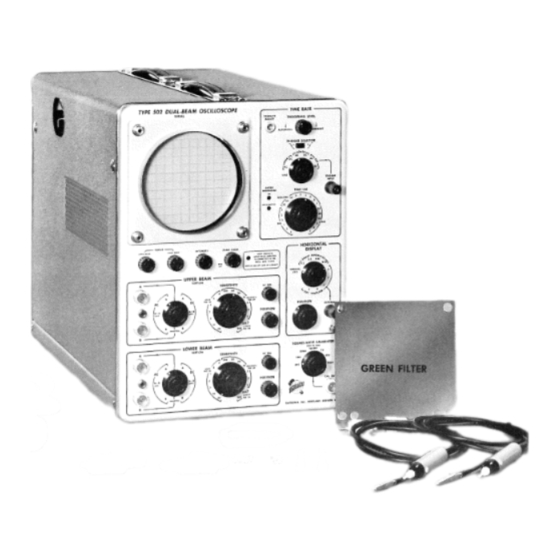
Introduction. Equipment Required. Low-Voltage Power Supply. Calibrator. CRT Circuit. Hori zontal Amplifier. Time-Base Generator. Vertical Amplifier. Triggering Circuit. PARTS LIST, BLOCK DIAGRAM and SCHEMATICS SECTION 7 ABBREVIATIONS & WARRANTY, PROBE, ACCESSORIES FOR TEKTRONIX INSTRUMENTS and SHORT FORM CATALOG TYPE 502... - Page 7 Fig. 1-1. Type 502 Oscilloscope with accessories...
-
Page 9: Specifications
The Tektronix Type 502 Oscilloscope provides linear dual-beam displays with a wide range of sweep rates combined with high in put sensitivity. In addition, the Type 502 may be used to provide dual-beam X-Y displays at medium sensitivities, and single-beam X-Y displays at high sensitivities. - Page 10 1 cm divisions with 2 mm markings 2—Type P510A attenuator probes on the baselines. 2— Type A510 binding post adapters Power requirements 1— Green filter Line voltage— 105 to 125 volts, or 210 to 250 1— Instruction Manual 1 -2 SPECIFICATIONS — TYPE 502 ®...
-
Page 11: Preliminary Instructions
The Type 502 is equipped with a special must be in place. Be sure the bottom power transformer. This transformer has a group p anel is installed according to direc of primary terminals whch allows you to connect tions. -
Page 12: Fuse Requirements
Fuse Requirements fer m Fost- ^ 0 j-a cyc\es us ' i k G f o „ Conn® c',ot'* • ed depend t f x g a s 1 » — > C ^ 0 - A W ° g v The manner jr U g . -
Page 13: Operating Instructions
OPERATING INSTRUCTIONS INPUT SELECTION On the Type 502 Oscilloscope, you can con Differential inputs must be connected to both the "A ” and “ B” input connectors of one ampli nect single-ended inputs to either the “ A ” or fier. - Page 14 An adjustable capacitor Type P510A Probes are furnished as acces in the probe body compensates for variations in sories to the Typo 502 oscilloscope. These input capacitance from one instrument to an probes are easily identified by their black, other.
- Page 15 This problem is not encountered in certain cases. With external triggering, the trig the dc mode since the triggering point is deter gering signal generally remains essentially con mined only by instantaneous voltages. © OPERATING INSTRUCTIONS — TYPE 502...
- Page 16 The TRIGGER SELECTOR switch deter mines whether the sweep is triggered on the rising ( + Fig. 3-4. Effects of TRIGGERING LEVEL and TRIGGER slope) portion, or the falling ( — slope) portion of the SELECTOR control settings. waveform. OPERATING INSTRUCTIONS — TYPE 502...
- Page 17 See Figure 3-4. FREE-RUNNING OPERATION With the Type 502, you can get a periodic, RECURRENT position. This permits you to ob free-running sweep, independent of any external serve the upper- and lower-beam traces without triggering or synchronizing signal by rotating the an input signal.
-
Page 18: Magnifier
EXTERNAL HORIZONTAL INPUT and differential input for both horizontal and On the Type 502, it is possible to horizontally deflect one or both of the spots across the screen vertical deflection. The lower beam is used for this function while the upper beam is auto... - Page 19 Accurate voltage measurements of inputs to the vertical amplifiers can be made using the calibrated deflection factor feature of the Type 502. The following instructions tell you how to use the oscilloscope for this purpose and how to obtain the greatest possible accuracy in your measurements.
- Page 20 By measuring the horizontal distance between points on the timebase feature of the Type 502 Oscilloscope. The sweeps are calibrated so that the beams are displayed waveform, and by knowing the sweep deflected across the screen at known rates.
- Page 21 WAVE CALIBRATOR switch settings for no load for the calibrator are made with the conditions. The primary function of the calibra assumption that the output cathode tor is to provide a convenient method for check follow er is conducting. OPERATING INSTRUCTIONS — TYPE 502...
- Page 22 1 megohm. The vertical The graticule of the Type 502 Oscilloscope can deflection plate pins are located on the sides of be illuminated so that it appears to have either the crt neck and the horizontal deflection plate red or white graticule markings.
- Page 23 20 times horizontal magnification of the dis beams horizontally. played waveform. Also controls horizontal EXTERNAL. Input connector for external signals sensitivity for external inputs applied at the which are applied to the horizontal ampli EXTERNAL connector. fier. 3 -n ® OPERATING INSTRUCTIONS — TYPE 502...
- Page 24 GND. Connector on the rear of the instrument BASE AMP position, this switch connects the which is used to provide a ground connec output of the horizontal amplifier to the tion to the CRT CATHODE connector. 3-12 ® OPERATING INSTRUCTIONS— TYPE 502...
-
Page 25: Circuit Description
X-Y oscilloscope. And, by The Type 502 circuitry is arranged so that the means of the EXTERNAL horizontal-input con instrument can be used in any of several config... - Page 26 Near the up per-frequency range of the Amplifier the imped When the Input Selector switch is in the A ance of the capacitors becomes so low, com position (either AC- or DC-coupled) the grid of CIRCUIT DESCRIPTION — TYPE 502 ®...
- Page 27 SENSITIVITY switch is in the .2 erate very close to ground (actually, a couple of VOLTS/CM position. ® CIRCUIT DESCRIPTION — TYPE 502...
- Page 28 In the quiescent state, that is, ready to receive When the switch is in the UPPER or LOWER posi a signal, V45A is conducting and its plate volt- CIRCUIT DESCRIPTION — TYPE 502...
- Page 29 V45B. The voltage at the grid of V45A CIRCUIT DESCRIPTION — TYPE 502...
- Page 30 Timing Capacitor. By means of the Timing Switch, both the size of cent voltage of about -f-32 volts at the plate of the capacitor being charged and the current the Miller Tube. CIRCUIT DESCRIPTION — TYPE 502...
- Page 31 As mentioned through a front-panel EXTERNAL connector rath previously, this is the action that initiates the re er than from the Time-Base circuits. CIRCUIT DESCRIPTION — TYPE 502...
- Page 32 N EG A TIV E FEEDBACK FROM TIM E-BASE G E N . N EG A TIV E FEEDBACK Fig. 4-2. Block diagram of the Horizontal Amplifier, illustrating the feed back loops. CIRCUIT DESCRIPTION — TYPE 502...
- Page 33 Plate and filament power for the tubes in the perly adjusted the output is exactly —150 volts. 502 Oscilloscope is furnished by a single power Should the loading on the supply tend to transformer T602. The primary has two equal change the output voltage, the voltage at the tapped windings;...
- Page 34 (at the faster sweep V814A; the cathode of this tube is connected to rates) the power supply itself is not appreciably the —150-volt regulated supply. The error volt moved. For longer unblanking pulses, at the 4-10 CIRCUIT DESCRIPTION — TYPE 502...
- Page 35 slower sweep-rates, however, the stray capaci adjusts the geometry of the display, and a single tance of the circuit is charged through R864. This INTENSITY control controls the brilliancy of both holds the grids at the unblanked potential for the beams.
-
Page 37: Maintenance
REMOVAL A N D REPLACEMENT OF PARTS Removal of Panels The procedures required for replacement of most parts in the Type 502 are obvious. Detailed The panels of the Type 502 Oscilloscope are instructions for their removal are therefore not held in place by small screwhead fasteners. - Page 38 It may also be pur normally not replaced on the switches used in chased directly from Tektronix in one-pound rolls the Type 502 and if one wafer is defective, the (order by part number 002-664). entire switch should be replaced. Switches may Because of the shape of the terminals on the be ordered from Tektronix either wired or un...
- Page 39 Standard Parts stallation. Replacements for all parts used in the Type 502 Oscilloscope can be purchased directly from Duplicate Parts Tektronix at current net prices. ‘ However, since most of the components are standard electronic The Type 502 contains virtually identical verti...
- Page 40 100 detailed voltage or resistance measurements. 100 series....Time-Base Generator Although the Type 502 Oscilloscope is a com and Timing Switch plex instrument, it can conveniently be thought 300 series....Horizontal Amplifier of as consisting of a number of interrelated basic 400 series....
- Page 41 Troubleshooting The L o w -V o lta g e Pow er Supply Proper operation of every circuit in the Type former is operating normally and the trouble lies 502 Oscilloscope depends on proper operation of somewhere in the secondary circuits. the Low-Voltage Power Supply. The regulated If only one of the outputs of the Low-Voltage voltages must remain within their specified toler...
- Page 42 3. For insufficient loading 2. AC bypass capacitors in the grid circuits of the regulator amplifiers If the output voltage is high with normal rip ple, check: 3. Regulator amplifiers screen grid circuits MAINTENANCE — TYPE 502 ®...
- Page 43 Due to the circuit configuration em be dangerous to human life. O u t ployed in the Type 502, it is possible for an in puts o f the Low V o lta g e Power Sup correct power supply voltage to affect one circuit ply are p articu larly dangerous due more than the others.
- Page 44 A nonlinear trouble; if the trace cannot be turned off with sweep can be caused by either the Time-Base the TRIGGERING LEVEL control, the Time-Base Generator or the Horizontal Amplifier. Generator is likely at fault. MAINTENANCE — TYPE 502 ®...
- Page 45 (resistors R129, R130, or R ill) or in the grid cir cause of this trouble can be obtained by measur cuit of V145A (resistors R141 or R143). ing the plate voltage of the Miller tube, V I61 A. 5-11 MAINTENANCE — TYPE 502 ©...
- Page 46 SWP LENGTH to reset the multivibrator (more positive than control R176, the resistance in the cathode circuit —35 volts). If this is so, and the multivibrator of V I61B should be checked. 5-12 MAINTENANCE — TYPE 502...
- Page 47 To determine the cause of this condi Procedure, if a trace (or spot) is visable when the tion, short the plates of the output stage (V474B vertical deflection plates are externally shorted and V484B) together. If the trace does not ap- MAINTENANCE — TYPE 502...
- Page 48 .. low frequency and high frequency. ing circuit. If tubes become gassy however, their resultant grid current will establish a time con- If a square wave is applied to an input of the 5-10 MAINTENANCE — TYPE 502 ©...
- Page 49 If the gain of the Horizontal Amplifier de creases, the trace will not extend to the left and 5-13 MAINTENANCE — TYPE 502 ®...
-
Page 51: Recalibration Procedure
RECALIBRATION PROCEDURE INTRODUCTION The following paragraphs outline the proce until specific instructions are given to disconnect dure used to recalibrate the Type 502 Oscillo them or until another input signal is applied to scope. The instrument should not require fre... - Page 52 .01 to 10 volts per divi sion and (2) bandpass of dc to 10 megacycles. 7. Tektronix Type P52, 52-ohm Coaxial Cable. Fig. 6-1. Tools required for calibrating the Type 502 8. Tektronix Type B52-R, 52-ohm Termination Oscilloscope.
-
Page 53: Calibrator
In waveform A the GEOM ADJ control is improperly set causing bowing of the vertical lines. In waveform B the bowing of the vertical lines has been reduced to a minimum by the proper adjustment of the GEOM ADJ control. © RECALIBRATION PROCEDURE — TYPE 502... - Page 54 I I I * Fig. 6-6. Adjustment of C311. Waveforms A and C result from improper settings of C 31 1. Capacitor C311 should be adjusted so that waveform B is obtained on the test oscilloscope. RECALIBRATION PROCEDURE — TYPE 502...
- Page 55 .2 M V /C M DIFF BAL control Waveform B shows a typical dis- similar to waveform A will be obtain* sted properly. play obtained when the control is adju RECALIBRATION PROCEDURE — TYPE 502...
- Page 56 Type 105 to input connector B of 23. C406A and C406C. Apply 1-kc square- the vertical amplifier through the CS47 Capaci tance Standardizer. Place the Input Selector waves from the Type 105 to input connector A RECALIBRATION PROCEDURE — TYPE 502 ®...
- Page 57 STABILITY ADJUST potentiometer to ground. Ro (See Fig. 6-11.) by placing a jumper between that tate the STABILITY ADJUST control clockwise point and the chassis. Adjust the TRIG. LEVEL from the fully counterclockwise position. Note RECALIBRATION PROCEDURE — TYPE 502...
- Page 58 LEVEL control in the RECURRENT position. Ad the + or — positions of the TRIGGER SELECTOR just the SWP LENGTH control for a total sweep Slope switch. length of 10.5 centimeters. RECALIBRATION PROCEDURE — TYPE 502 ©...
- Page 59 ABBREVIATIONS & WARRANTY. It is recommended that those components marked with an asterisk in fron t o f the Part Number be purchased from the factory or from a Tektronix Field Engineering O ffice. Tektronix LAMPS...
- Page 60 .0068 /if 283-518 330 /i/if Mica Fixed 500 v C871 283-518 Mica Fixed 500 v C876 330 /i/if tThere are two parts of this description in your instrument; one in each of the Vertical Amplifiers. PARTS LIST — TYPE 502...
- Page 61 Fixed Comp. R160A 1 meg Fixed Film *309-014 R160B 2 meg Fixed Film *309-023 *309-087 R160C 5 meg Fixed Film R160D *309-095 10 meg Fixed Film R160E 10 meg Fixed Film *309-095 7 -3 ® PARTS LIST — TYPE 502...
- Page 62 Resistors (continued) Fixed Film *310-061 R160F 15 meg *310-061 Fixed Film R160G 15 meg 302-101 Fixed Comp. 100ft R161 306-154 Fixed Comp. 150 k R166 Comp. 302-155 Fixed 1.5 meg R167 Fixed Comp. 302-472 4.7 k R168 302-101 Fixed Comp. R169 100 ft 306-273...
- Page 63 Comp. R433t 302-223 Comp. Fixed R434t 22 k y2 w *311-125 Comp. 50 k 0.2 w Var. R435t tThere are two parts of this description in your instrument; one in each of the Vertical Amplifiers. PARTS LIST — TYPE 502...
- Page 64 R623 50 k 302-333 Comp. Fixed 33 k R630 302-105 Comp. Fixed 1 meg R631 tThere are two parts of this description in your instrument; one in each of the Vertical Amplifiers. 7 -6 PARTS LIST — TYPE 502 ®...
- Page 65 1 0 % R806 3.9 k Fixed Comp. 302-392 1 0 % R808 /■-£ V2k Fixed Comp. 306-122 1 0 % R809 470 k Fixed Comp. 302-474 1 0 % R820 Fixed Comp. 302-102 1 0 % 7»7 PARTS LIST TYPE 502...
- Page 66 900 0 Fixed Film R888 309-238 90 0 Fixed Film R889 Film 309-096 R890 1 00 Fixed Manufactured by Tektronix 308-090 R899 0.25 O Tektronix RECTBFIERS Part Number *106-001 1-500 ma plate/leg SR642 PARTS LIST — TYPE 5 0 2 ®...
- Page 67 Telefunken tubes are recommended. 154-039 V484A,Bt V493 6AU6 154-022 V602t 5AR4 154-168 V634 2N214 (Transistor) 151-004 V636A,B 6AN8 154-078 tThere are two parts of this description in your instrument; one in each of the Vertical Amplifiers. PARTS LIST — TYPE 502...
- Page 68 154-168 V722 6AN8 154-168 V746A/B 154-044 V747 12B4 12B4 154-044 V757 154-167 V800 6CZ5 12AU7 154-041 V814A,B 154-051 V822 5642 T66P2 (CRT) 154-144 V859 154-051 V862 5642 154-078 V873A,B 6AN8 V875 6AU6 154-022 7-10 PARTS LIST — TYPE 502 ®...
- Page 69 Ground strap, CRT cathode 386-427 Holder, neon, double *352-006 Holder, neon, single *352-008 Knob, black: TRIGGER SELECTOR, HORIZONTAL DISPLAY, (HORIZ.) POSITION, SQUARE-WAVE CALIBRATOR, (VERT.) AC-DC *366-028 Knob, black: FOCUS, INTENSITY, SCALE ILLUM., TRIGGERING LEVEL, (VERT.) POSITION *366-033 7-11 MISC PARTS — TYPE 502...
- Page 70 136-050 Socket, STM7G, 7 pin 136-008 Socket, 7 pin, shielded 136-010 Socket, STM9G, 9 pin 136-015 Socket, CRT, STM14, 14 pin 136-019 Shock mount, vertical chassis *348-022 Shock mount, fan *348-008 Test lead *012-031 7-12 MISC PARTS — TYPE 502...
- Page 71 • n r r r r r r n r : l ^ T T V V V Y V ; I T T ' V - 124-066 124-065 124-071 124-012 124-016 129-009 .^rrrrrrri“rrri Ceramic Strips and Ceramic Post. 7-13 ® MISC PARTS — TYPE 502...
- Page 72 CRT Alignment Ring. Graticule Light, CRT, Tube and Transistor Sockets. Grounding Assy., Tips and Clip Assy, for Probes. Coax Receptacle Assy., Control Rod Coupling and Shockmounts. 7 - 14 ® MISC PARTS — TYPE 502...
- Page 73 (24 L) C406J (25L) C407A (26L) C407J (24L) C 4 0 6 G (25L) C407C (23L) C 4 0 6 C (23 L) C 4 0 6 A (31) TRIG LEVE (29L) FEE D BAC K BAL (17L) DIFF .2 V / C M (18L) .2 DIFF BAL M V / C M...
- Page 74 (11) EXT HORIZ AMPL DC BAL (10) N O R M /M A G REGIS (35) SWP LENGTH (5) GEOM ADJ (23L) C406C (9) X I CAL (6) ASTIG LOWER (8) X 20 CAL (6) ASTIG UPPER (23 L) C 406A (31) TRIG LEVEL CENT (12) C 3 1 1 (7) INT BAL...
- Page 75 Recalibration Procedure when the control is set. The letters L and U following the step number indicate whether Fig 6-14 Type 502 Oscilloscope, right and left views show the adjustment is for the Upper-Beam Amplifier or for the Lower- ing the location of Recalibration controls.
- Page 76 J) DC BAL ) DC BAL (23 U) C 406C (24U) C 4 0 6 G (24U) C 406J (2 6 U (2) CAL ADJ Fig 6-14 Type 502 Oscilloscope, right and left views show ing the location of Recalibration controls.
- Page 77 BLOCK DIAGRAM TYPE 502 OSCILLOSCOPE...
- Page 78 — , ^ L L » O O o o o o < N C M O o o O O O ^ ^ ^ ^ ^ 2 ^ ;3 Q£ Q£ o ' O ' J *5 cfaL 6 F&R R408M- iiiu : R408C-...
- Page 79 SECOND D R IV E R O UTPUT INPUT A M PLIFIE R A M PLIFIE R C F’S AM PLIFIE R X 10 X 100...
- Page 80 .001 MODIFICATION NOTICE FOR TYPE 502 E FFECTIVE SERIAL NO ADD C11 e001/<F 500V DISCAP 283-000 R 11 47OK 1/2W FIXED COMP \0% 302-474...
- Page 81 - t - ~ (UPPER BEAM VERT. AMP.) FROMCATH., PIN 7, V 493 INTERNAL TRIG. C F INTERNAL TRIli. ' . r - - r - (LOV/ER BEAM VERT. AMP.) ,----- O AC TIME-BASE TRIGGER j INPUT 1 Y TYPE 502 OSCILLOSCOPE...
- Page 82 V722 type 502 HEATER WIRING DIAGRAM POWER SUPPLY o s c i l l o s c o p e...
- Page 83 N O T E U nless otherw ise specified, all of the voltage read ings w ere taken w ith a dc vacuum -tube voltm eter having an input resistance of 11 m egohm s. T he w ave form s shown w ere reproduced from actual photo graphs.
- Page 84 T801 TRANSFO RM ER CONNECTIONS Sea p a r t s l i s t f o r l at e o o r n p o n e n t - v a l u e c h a n g e s CRT CIRCUIT TYPE 5 0 2 OSCILLOSCOPE...
- Page 85 R331N R331M SWITCH DETAIL F & R 1 F&R N O T E i f i e i t h i l l - t u i f i c l t s l t a HORIZONTAL DISPLAY SWITCH l t a i t i o Right-side V iew l t a...
- Page 86 O UTPUT A M P LIFIE R S W E EP W AVEFORM FROMCATH., PIN3.V 16TB _ RUNUP CF (TIM E-BASE GEN. DIAG.) VO LTAG E R EADINGS were obtained V/ITH CONTROLS S E T AS FOLLOWS: HORIZONTAL DISPLAY....NORMAL ....
- Page 87 N O T E U nless otherw ise specified, all of the voltage read ings w ere taken w ith a dc vacuum -tube v oltm eter having an input resistance of 11 m egohm s. T h e w ave forms shown w ere reproduced from actual pho to ...
- Page 88 N O T E Unless otherw ise specified, all of the voltage read ings were taken w ith a dc vacuum -tube voltm eter having an input resistance of 11 m egohms. T he w ave forms shown were reproduced from actual photo graphs.
- Page 89 SW EEP-GATING M ULTIVIBRATO R CO NTROL S E E ALSO AUTOMATIC TRIGGERING CO NTROL (TIM E-BASE TRIG . DIAG.) TYPE 5 0 2 OSCILLOSCOPE...
- Page 90 M ILLE R RUNUP CIRCU IT + 350 V M ILUSEC TIME-BASE GENERATOR 12-8-58...
- Page 91 ----------3 F&R 4 F&R C160A C160D ----------C180C R160A ----- Cl SOD 1 F&R 2 F&R Black, Green on Brown SW 331, — 150 ----- R180A Brown on whitel Red on white R180B To SW331, 5F Orange on White Cl 81 R160E Yellow on White C180A...
- Page 92 -TIMING CAPACITORS [-*-------------------------HOLD-OFF CAPACITORS & RESISTORS -TIMING RESISTORS - SW 160 -| TIME/CM \- 4F&R TIMING SWITCH TYPE 502 OSCILLOSCOPE...
- Page 93 R886- R885- To CAL. OUTs connector ( ground side) N ' O T E Unless otherwise specified, all of the voltage read ings were taken w ith a dc vacuum-tube voltmeter having an input resistance of 11 megohms. The wave- forms shown were reproduced from actual photo...
- Page 94 CALIBRATOR MULTIVIBRATOR TYPE 502 OSCILLOSCOPE...
- Page 95 CAL. OUT WAVEFORMS VOLTAGE READINGS' a n d WERE OBTAINED WITH CONTROLS SET AS FOLLOWS: SQUARE-WAVE CALIBRATOR 100 V ‘VOLTAGE READINGS MAY VARY WITH CALIBRATOR DUTY CYCLE V873B V 2 6 A N 8 I CAL. OUT I ? R 899 See parts list for late component-value changes CALIBRATOR...
- Page 96 ABBREVIATIONS USED IN OUR PARTS LISTS ceramic Cer. milli Comp. composition electrolytic, metal cased Poly. polystyrene electrolytic, metal tubular Prec. precision farad paper tubular henry Tub. tubular thousands of ohms working volts dc megohms Var. variable micro watt micromicro wire wound { 1 [ X guaranteed minimum value ABBREVIATIONS USED...
- Page 97 SERIAL NO. _ O c C l l Include the IN S T R U M K P E and the above S E R I A L N U M B E R in any correspondence regarding this instrum ent. T h e above serial num ber m ust match the instrum ent serial n um ber if parts are to be ordered from the m anual.
- Page 98 S C R E W D R IV E R A D J U S T C O A X IA L C A B L E IN P U T 10 M E G . S H U N T E D j ju W H E N C A B L E...
- Page 99 30 v miniature battery, included with the instrument. GENERAL DESCRIPTION P r i c e ................$ 5 0 The Tektronix Type 123 Preamplifier is a compact, Includes: 1— Mercury cell light-weight, battery-operated amplifier for use in appli 1— B battery cations where a gain of without additional hum sig...
- Page 100 1 /xsec, and amplitude is 2 v positive. Trigger Mounting frame— provides secure mounting to the top ing may be accomplished by the composite video signal of Tektronix 5" Oscilloscopes. of either polarity, 0.5 v minimum to 20 v maximum, peak Connecting cables— the four connecting cables sup...
- Page 101 Electronic V o ltag e Regulation GENERAL DESCRIPTION The Tektronix Type 1 26 Power Supply supplies the re quired voltages and currents necessary to power one Type 360 Indicator or any one of the Type 160-Series Waveform Generators. The Type 126 mounts beneath the unit to be powered, and includes a cabinet to house both the Type 126 and the powered unit.
- Page 102 O p e ra tio n a l Accessories SCOPE-MOBILE The Tektronix Type 500 Scope-Mobile is a sturdy, mo The Tektronix Type 5 0 0 /5 3 Scope-Mobile is the Type bile support for Tektronix 5 " Oscilloscopes. Convenient 500 with a Type 53 Scope-Mobile front-panel installed.
- Page 103 ACCESSORIES O p e ra tio n a l Accessories B52-T10 52-ohm ‘T’ pad, 10 to 1 voltage ratio. 1.5 w ............11.50 B75-R 75-ohm terminating resistor, 1.5 w . . 8.50 011 023 75-ohm terminating resistor for Type 525, 0.5 w ........ 4.00 B75-L5 75-ohm T pad, 5 to 1 voltage ratio,...
- Page 104 Type 513 to rectify the 6.3 P510A Attenuator Probe provides an attenuation of volt heater supply. ten times when used with Tektronix oscilloscopes and am KP170CF DC Filament Kit for Type 5 1 3 ....4.50 plifiers.
- Page 105 Provides a frequency stability of 2 ppm over a 24-hour period ................27.00 CC 310 Canvas Carrying Case, for Tektronix Type 310 Oscilloscope. The case has a zipper fastener along the HC 310 Collapsible Viewing Hood, for Tektronix 3" top and one end. The other end is padded for extra pro...
- Page 106 ACCESSORIES O p e ra tio n a l Accessories Coaxial cable, 75 ohms nominal imped ance, 4 2 " lo n g ..........4.00 Coaxial cable, 93 ohms nominal imped ance, 4 2 " lo n g ..........4.00 P93A Coaxial output cable, 93 ohms, termin...
- Page 107 D E S C R I P T I O N placed on the shape of the positive portion of the wave The Tektronix Type 107 Square-Wave Generator is form. Therefore, only this portion should be used in tran basically intended as a Test Accessory for the Type 540- sient response testing.
- Page 108 ACCESSORIES Test Accessories f " 015-001 (S30) Delta Standards, for calibration of the Type 130 L,C Meter. The unit provides accurately 01 3-00 5 (EP53A) Gain Set Adapter— Permits an ex adjusted steps of capacitance and inductance, selected ternal calibrating signal to bypass the plug-in preampli by a rotary selector switch.
- Page 109 ACCESSORIES Replacem ent Parts GRATICULES 3 7 8-50 5 Green (for Type 315 D ) ......50 3 " 37 8 -5 0 7 3" Blue (for Type 3 1 5 D ) ........50 386-39 5 Unruled, for Type 3 1 0 ......1.00 378-501 (F 510-3) 5 "...
- Page 110 ACCESSORIES R e p la c e m e n t P a rts IN STRUCTION M A N U A LS 514 or 5 1 4 D ..............2.75 514A or 5 1 4 A D ............3.00 104A ................
- Page 111 APPROXIMATE SHIPPING WEIGHTS D O M E S T IC E X P O R T P A C K E D IN S T R U M E N T N E T W E IG H T P A C K E D W E IG H T I N V O L U M E I N T Y P E...
- Page 112 Kits are designed to cover please direct all inquiries and orders to the TEKTRONIX expected needs of a group of ten instruments of the DISTRIBUTOR in your country. Customers in a country not same type.
- Page 113 If you are responsible for the maintenance of a large quanti area. Your Field Engineer can ty of Tektronix Instruments, ask your Field Engineer about the help you select the one best free factory training course in maintenance and calibration.
- Page 114 Tektronix, Inc., P. O. Box 831, Portland 7, Oregon Telephone: CYpress 2 -2 6 1 1 T W X — PD 311 C able: TEKTRONIX AN OREGON CORPORATION Field Engineering Offices Inc., 1 2 7 C Je ffe rso n St. N . E., A lb u q u e rq u e , N e w M e x ic o T W X —...
Need help?
Do you have a question about the 502 and is the answer not in the manual?
Questions and answers