Advertisement
Quick Links
Advertisement

Subscribe to Our Youtube Channel
Related Manuals for Tektronix 561A

Summary of Contents for Tektronix 561A
- Page 1 NSTRUCT ON MANUAL 561A SCILL SC PE ektronix, Inc. .W. Millikan Way • P. O. Box 500 • Beaverton, Oregon • Phone Ml 4-0161 • Cables: Tektronix ektronix International A. G. Terrassenweg 1A • Zug, witzerland • PH 042-49192 •...
-
Page 2: Table Of Contents
Section 5 Calibration Section 6 Accessories Section 7 Parts List and Schematics Copyright ® 1962 by Tektronix, nc., Beaverton, Oregon. Printed in the United States of America. All rights reserved. Contents of this publication may not be re produced in any form without permission of the copyright owner. -
Page 3: Warranty
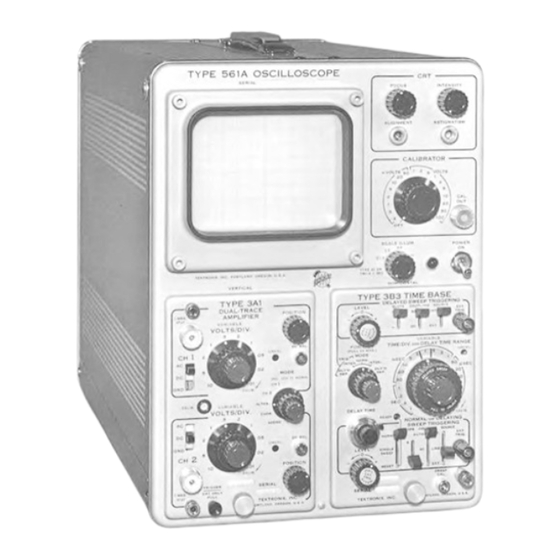
WARRANTY All Tektronix instruments are warranted against defective materials and workman ship for one year. Tektronix transformers, manufactured in our own plant, are war ranted for the life of the instrument. Any questions with respect to the war ... - Page 4 The Typo 561 A Oscilloscope. including the Type 3A1 Dual-Trace Amplifier and the Type 383 Time Base. Type 561 A ttp://manoman.sq ill.com...
- Page 5 (X-axis) deflection, and the plug-in unit in Risetime — Typically 4 microseconds. the left-hand opening controls the vertical (Y-axis) deflectic n. The plug-in units can be selected from any of the Tektronix eries or '3' eries groups to provide the desired oscillo ...
-
Page 6: Operating Nstructions
Cooling. Operation Operation of the Tektronix Type 561 A Oscilloscope with two plug-in units in place is much the same as that of a conventional Tektronix oscilloscope with corresponding verti ... - Page 7 Intensity (Z-axis) modulation of the crt beam is possible through the EXT. CRT. CATHODE binding post on the rear To insert a plug-in unit into the Type 561A Oscilloscope, of the instrument. Depending on the setting of the INTEN ...
-
Page 8: Circuit Description
V627 will cause the load current to change in the direction needed to bring the output back to The Tektronix Type 561 A Oscilloscope contains a lo v- — 100 volts. C616 improves the response of the regulator to voltage power supply circuit, a cathode-ray-tube circuit, sudden changes in output voltage. - Page 9 Connectors diagram) are set at the factory for an effective Cathode-Ray Tube deflection-plate capacity of 16 picofarads for each plug-in. A Tektronix T561 ceramic-envelope cathode-ray tube is used in the Type 561 A. The accelerating potential is ap proximately 3500 volts, developed by about — 3300 voits at...
-
Page 10: Maintenance
Next, the trouble is isolated to is probably in that unit. a plug-in unit or to the Type 561A. Trouble in the T)pe 561 A is then localized to the Power upply, Crt Circuit, or... - Page 11 Tube failure is the most prevalent cause of trouble in measurements. Voltages at various points throughout the Tektronix instruments Therefore, if a visuol check fails instrument are indicated on the circuit diagrams ond in Figs. to reveal the cause of trouble, all tubes should be checked 4-1, 4-2 and 4-3.
- Page 12 Maintenance — Type 561 A 3400 — 3100 v — 215 v 2000 v — 3450 » — 3300 v — 82 v |31| — 106v |30| — 2900 v + 0 Sv 4- 125 v 1 35 1 | 21 | -3300v H V, TEST PO NT (pin 13 of...
- Page 13 Maintenance — Type 561 A TABLE 4-1 SYMPTOMS PROBABLE CAUSES CHECKS TO MAKE — 100-Volt Power Supply 1. Output voltage slightly higher or lower Improper setting of R616. 1. Use the — 100 V adjustment to try to than normal but regulates with changes set the output voltage to normal.
- Page 14 Maintenance — Type 561 A (TABLE 4-1 cont ’ d) SYMPTOMS PROBABLE CAUSES CHECKS TO MAKE — 12.2-Volt Power Supply (continued) 6. Check D720 and D721, and C720A and C720B. 7. Check voltage across Q734; should be near 13.5 volts. 8.
- Page 15 Maintenance — Type 561 A 4-1 cont ’ d) able PROBABLE CAUSES SYMPTOMS CHECKS TO MAKE Calibrator V884 defective. 1. Check de voltage at test point [41]. 1. No output from Calibrator. Voltage will probably be either 0 or Open resistor. -f-100 volts.
- Page 16 The silver-bearing solder is locally available in most Soldering Precautions areas, or it may be purchased directly from Tektronix in In the production of Tektronix instruments a special one-pound rolls (order by part number 251-514). Occasional...
-
Page 17: Calibration
Type volts). Allow the equipment to warm up for about 10 561A. Connect the output of the Calibrator to the vertical minutes. amplifier and adjust the time-base unit to display two to five cycles of the Calibrator signal. - Page 18 Calibration — Type 561 A Cl and C3 are fixed for the vertical system. C2 is adjust able by means of C760. etting C e ff equal to 16 pico farads and solving for C2: C2 = 32 pf - (Cl + 4C3). Thus, by measuring Cl and C3, you can determine the desired value of C2 for the vertical system.
-
Page 19: Accessories
Additional plug-in units and other accessories will be made available os new applica tions develop. If you are faced with a measurement problem which is not solved ade quately by existing Tektronix plug in units or combinations of plug-in units and amplifiers, consult your local Tektronix Field Engineer. - Page 20 Table 6-3. ( ignals take nominally 5 nsec to poss through 40" of 50-ohm cable.) NTERCONNECT NG LEADS everal types of interconnecting leads ore listed in Table 6-4. These are valuable when patching between circuits or between panel connectors of Tektronix oscilloscopes. ttp://manoman.sq ill.com...
- Page 21 H GH FREQUENCY BNC CONNECTOR TERM NAT ONS AND ATTENUATORS Tektronix offers a series of terminating resistors and atten uators, having a BNC Plug on one end ond o BNC Jack on the other. The attenuators have o «wr of less than 1.1, when...
- Page 22 Accessories — Type 561 A Observe the power rating stamped on the case of the ter Replacement resistance elements are listed with the units. minations and attenua'ors. Power dissipation in excess of To disassemble, remove the four screws from the p ’ ug end, the rating) may destroy the resistance clement inside the unsolder the lead in the plug center conductor and remove unit.
- Page 23 % values. Thus the input resistance when 50!? Termination Resistor, 1.5 watts. Unit; 011 045 using the P6026 with a Tektronix 50-ohm sampling system is Replaces: 011 001 within 2%. Elements: 2, 309-372 75 LI Termination Resistor, 1.5 watts. Unit:...
- Page 24 Trigger Probe is a trigger-coupling probe for external trig input resistance instruments The 42 inch cable leng ’ h P6017 gering of Tektronix sampling system timing units. The Type and P6022 Probes provides uniform amplitude response with P6033 accepts triggering signals with risetimes as fast as no overshoot or ringing.
- Page 25 Accessories — Type 561 A A compensating box at the oscilloscope end of the probe P6016 Current Probe System — The P6016 Current cable enables the P6013 to be properly compensated to Probe with the Type 131 Current Probe Amplifier or the any oscilloscope having an input resistance of one megohm Passive Termination constitute on ac current detecting sys ...
- Page 26 003-007 Tektronix recalibration tool assembly. This 4-unit tool assembly provides most of the necessory tools far adjusting variable inductors in Tektronix instru ments. 003-301 Walsco Nc. 2543 double-ended 0.1" hexagonal wrench. This tool is useful for adiusting variable in- dutors with hexagonal cores.
- Page 27 C-19 particularly suitable for Type 107 Square-Wave Generator applications requiring extremely high writing rales. Other lenses currently available from Tektronix may be used with Risetime Loss than 3 nsec with 50 ohm internal termination the C-19 Frequency Range 400 kc to 1 me, uncolibratcd.
- Page 28 Accessories — Type 561 A Type 109 Pulse Generator Pulse Repetition Rate — 10pps to 100 kc In 4 ranges with continuously variable control. Pulse Risetime — Less than 0 .25 nsec. Pulse Amplitude — More than ±5 volts. Pulse Length — Minimum of approximately 0.5 nsec to a Pretrigger Pulse Charateristics —...
- Page 29 Accessories — Type 561 A Type 1 30 L-C Meter Type 181 Time-Mark Generator Guard Voltage — Permits measuring an unknown capacitance Time-Marks — 1, 10, 1000, and 10,000 « sec, plus 10-mc sine while eliminating the effects of other capacitances from the wove.
- Page 30 Field ffice. The composite experience of 350 mon years of Field Engineering, solving problems similar to yours, is available to you as a Tektronix Customer. The Field Engi neat responsible for your area is always looking lor a now challenge.
-
Page 31: Parts List And Schematics
X000 Part first added at this serial number. 000X Part removed after this .erial number. + 000-000 Asterisk preceding Tektronix Part Number indicates manufactured by or for Tektronix, also reworked or checked components. Use 000-000 Part number indicated is direct replacement. - Page 32 Parts List — Type 561 A HOW TO ORDER PARTS Replacement parts are available from or through your local Tektronix Field Office. Changes to Tektronix instruments are sometimes made to accommo date improved components as they become available, and to give you the benefit of the latest circuit improvements developed in our engineer ...
- Page 33 Parts List — Type 561 A ELECTR CAL PARTS L ST Values are fixed unless marked Variable. Tektronix Ckt. No. Part Number Description /N Range BULBS B601 150-001 Incandescent, G.E. #47 Graticule Light B602 150-001 Incandescent, G.E. #47 Graticule Light...
- Page 34 Parts List — Type 561 A D ODES Tektronix Ckt. No. Part Number Description /N Range D640A,B,C,D 152-047 ilicon 1N2862 D642A,B,C,D 152-047 ilicon 1N2862 D644A,B,C,D 152-047 ilicon 1N2862 D720 152-035 ilicon 1N1563A D721 152-035 ilicon 1N1563A D838 152-008 Germanium T12G...
- Page 35 Parts List — Type 561 A RES STORS (Cont'd) Tektronix Ckt. No. Part Number Description /N Range R644 304-100 10(2 5501-5562X R650 309-101 330 k 'A w Prec. R651 309-162 250 k Prec. R652 302-102 'A w R653 302-225 2.2 meg...
- Page 36 Parts List — Type 561 A RES STORS (Cont ’ d) Tektronix Description /N Range Ckt. No. Part Number y 2 * R839 302-104 100 k R840 301-125 1.2 meg ’ / 2 w HIGH VOLTAGE R841 311-042 2 meg Var.
- Page 37 Parts List — Type 561 A THERMAL CUTOUT Tektronix Ckt. No. /N Range Part Number Description TK601 260-071 Thermal Cutout 155° TRANSFORMERS T601 *120-280 L. V. Power T801 *120-275 H. V. Power TRANS STORS Q624 151-087 J3138 Q734 151-040 2N1302...
- Page 38 Parts List — Type 561 A Mechanical Parts List (continued) Tektronix Part Number Bracket, transformer 406-617 406-635 Bracket, low-capacity pot mounting, delrin Bracket, parallax adj. 406-730 Bushing, aluminum, 3 / 8 -32 x ’ / 16 x .412 358-010 Bushing, binding post, charcoal...
- Page 39 Parts List — Type 561 A Mechanical Parts List (continued) Tektronix Part Number 352-031 Holder, single fuse Holder, coil form, CRT, poly, black 352-044 352-049 Holder, reflector shield 366-113 Knob, small, charcoal 366-117 Knob, large charcoal 210-004 Lockwasher, #4 int.
- Page 40 Parts List — Type 561 A Mechanical Parts List (continued) Tektronix Part Number Panel, front 333-710 Plate, ground, plated, open end 386-427 387-294 Plate, bottom cabinet Plate, cabinet side 387-300 Plate, gusset 387-352 387-681 Plate, front subpanel Plate, rear subpanel...
- Page 41 Parts List — Type 561 A Mechanical Parts List (continued) Tektronix Part Number crew, 8-32 x % TH 212-039 212-040 crew, 8-32 x % FH phillips 213-041 crew, 6-32 x % TH phillips, thread cutting 213-044 crew, 5-32 x 3 / 16 PH...
- Page 42 Parts List — Type 561 A Mechanical Parts List (continued) Tektronix Part Number Washer, steel, 6L x % x .032 210-803 Washer, brass, resistor centering 210-808 Washer, #10 fiber 210-812 Washer, steel, .390 x x .020 210-840 Washer, brass, 5 / 32 x ’ / 2 x '/ 16 thick 210-858 Washer, rubber, ’...
- Page 43 + 6V + L.C72O + 3OOV 15 V PR MAR ES CONNECTED 2X 2OOO,uf FOR 234V OPERAT ON Q744 R734 2 A (SLOW-BLOW) 2NI378 33OK R73B Q757 2.7K THERMAL Q734 2NI 52e CUTOUT +4TO+8 2NI3O2 < AAA, R-7B7 2.O5K 1 — r-<5 £744 TK6O R732...
- Page 44 (Wh.) T801 TERM NALS & CONNECT ONS...
- Page 45 + 125V OSC LLATOR NTENS FY NG PULSE IXH — <14 <3>J2i + 3OOV R8O2 5.GK R805 27 K ALlGNMgNT| C8O3 ERROR S GNAL AMPL F ERS [33] +30OV +3OOV R8 5 V8I4A 47OK HI2BH7 E32] ------------------ Wv R 840 R8l5 -2.1 1.2 M...
- Page 46 + 150 5 m SEC/D V R87O R.B83 AMPL. V884B* 7 2 £>BLB CAL! BRATOR POWER. CONNECTOR V884A* PLUq TO F T 9 P N M N ATURE '/ 2 <&BL8 TUBE SOCKET + BOOV R879 4- 125V - OOV V884 C87fe e>.25>5...
- Page 47 R GHT HAND 07 ^2 7 <62 PLUG-IN CONNECTOR TYPE 561 A O CILLO COPE...
- Page 48 MANUAL CHANGE NFORMAT ON At Tektronix, we continually strive to keep up with latest electronic developments by adding circuit and component improvements to our instruments as soon as they are developed and tested. due to printing and shipping require ...
- Page 49 MOD 6860 Type 561 A - Tent S/N 7860 Type RM561A - Tent S/N 5280 131-279 Connectors Change to Chassis Mtg.
- Page 50 TYPES 561A-210C, 561A, MOD 7052 Tent S/N 7750 R835 Change to a series unit consisting of 5.6m 306-565 6.8m 306-685 Change to a series unit consisting of R842 2.7m 306-275 3.3m 306-335...
- Page 51 TYPE 561A - 561A,210C MOD 6467 - Tent S/N 6630 (47) R655 6.8m l/2w 302-685 500k Comp 311-068 Pot. R656 8.2m 302-825 R675 l/2w 500k Comp. 311-068 R676 Pot. 500k Comp. 311-068 R730 Pot. 560k 302-564 R733 l/2w As per schematic attached.
- Page 52 RT5I RT.5O -IOOV -IOOV -IOOV I I ' £>2 ART. WR. S LV. DIAQ.
- Page 53 TYPE 561A - RM561A Mod 6936 - 561 A - Tent S/N 7490 Mod 6936 - RM561A - Tent S/N 5160 Change to 390k l/2w 301-394 R733 l/2w 302-823 R729 As per schematic below, -100V...
-
Page 54: Type 561A
COMM TTED TO EXCELLENCE NSTRUCT ONS FOR REPLAC NG GLASS CRT ’ s W TH ONE OF THE FOLLOW NG CERAM C CRT's: Part No. 154-0613-00/02/03, 154-0614-00/02/03 TYPE T5032 CRT REPLACEMENT For the following Tektronix Oscilloscopes: Type erial Number 561 A 5001-12399*... - Page 55 3. Remove the CRT socket connector and loosen the clamp at the base of the CRT. 4. Remove the CRT. 5. Remove the CRT cushions, 4 (for Type 561A, RM561A, 567, RM567) or 6 (Type 568, R568) from the inside of the CRT shield. 6. Install the new CRT.
Need help?
Do you have a question about the 561A and is the answer not in the manual?
Questions and answers