
Related Manuals for Belden Grass Valley IPVU


Summary of Contents for Belden Grass Valley IPVU
- Page 1 IPVU Compact IP Monitoring Gateway Installation Guide 13-03068-010-M00 AA 2019-07-22...
- Page 2 Belden Inc. or its affiliated companies in the United States and other jurisdictions. Grass Valley, IPVU, Kaleido, Grass Valley are trademarks or registered trademarks of Belden Inc., and other parties may also have trademark rights in other terms used herein.
- Page 3 IPVU Installation Guide Important Safety Information This section provides important safety guidelines for operators and service personnel. Specific warnings and cautions appear throughout the manual where they apply. Please read and follow this important information, especially those instructions related to the risk of electric shock or injury to persons.
- Page 4 Notices The presence of this symbol in or on Grass Valley equipment means that it has been tested and certified as complying with applicable Intertek Testing Services regulations and recommendations for USA/Canada. The presence of this symbol in or on Grass Valley product means that it complies with all applicable European Union (CE) directives.
- Page 5 IPVU Installation Guide Cautions A caution indicates a possible hazard to equipment that could result in equipment damage. Observe the following cautions when operating or working on this equipment: • This equipment is meant to be installed in a restricted access location. •...
- Page 6 Notices Mesures de sécurité et avis importants La présente section fournit des consignes de sécurité importantes pour les opérateurs et le personnel de service. Des avertissements ou mises en garde spécifiques figurent dans le manuel, dans les sections où ils s’appliquent. Prenez le temps de bien lire les consignes et assurez-vous de les respecter, en particulier celles qui sont destinées à...
- Page 7 IPVU Installation Guide La marque C-UL-US certifie que l’appareil visé a été testé par Underwriters Laboratory (UL) et reconnu conforme aux exigences applicables en matière de sécurité électrique en vigueur au Canada et aux États-Unis. La marque ETL Listed d’Intertek pour le marché Nord-Américain certifie que l’appareil visé...
- Page 8 Notices • Ne pas utiliser cet appareil dans une atmosphère explosive. • Présence possible de courants de fuite. Un raccordement à la masse est indispensable avant la mise sous tension. • Après tout travail d’entretien ou de réparation, faites effectuer des contrôles de sécurité par le personnel technique qualifié.
- Page 9 IPVU Installation Guide • Portez un bracelet antistatique et assurez-vous qu'il est bien en contact avec la peau. Connectez la pince de masse à une surface non peinte du châssis pour détourner à la terre toute tension électrostatique indésirable. En l’absence de bracelet antistatique, déchargez l’électricité...
- Page 10 Notices Laser Safety - Fiber Output SFP and QSFP Modules Warning LASER SAFETY The average optical output power does not exceed 0 dBm (1mW) under normal operating conditions. Unused optical outputs should be covered to prevent direct exposure to the laser beam.
- Page 11 IPVU Installation Guide Information Technology Equipment - Safety Part 1 EN60950-1: 2006 Safety of Information Technology Equipment Including Electrical Business Equipment. UL1419 (4 Edition) Standard for Safety – Professional Video and Audio equipment (UL file number E193966) EMC Standards This unit conforms to the following standards: EN55032:2015 (Class A) Electromagnetic Compatibility of multimedia equipment - Emission requirements EN61000-3-2:2014 (Class A)
- Page 12 SFP+ type ports; and fit 75 Ώ RF terminators to BNC type ports. COAXIAL CABLES Coaxial cables connections (particularly serial digital video connections) shall be made with high-quality double-screened coaxial cables such as Belden 8281 or BBC type PSF1/2M and Belden 1694A (for 3Gbps). D-TYPE CONNECTORS D-type connectors shall have metal shells making good RF contact with the cable screen.
-
Page 13: Table Of Contents
Table of Contents 1 Introduction ............17 Overview. - Page 14 Table of Contents IPVU Mounting Orientation for a Wall-Mounted Monitor........42 Mounting an IPVU onto a VESA 75mm or 100mm Stand-Mounted Monitor .
- Page 15 IPVU Installation Guide 5 Maintenance & Troubleshooting ........83 Maintenance .
- Page 16 Table of Contents...
-
Page 17: Introduction
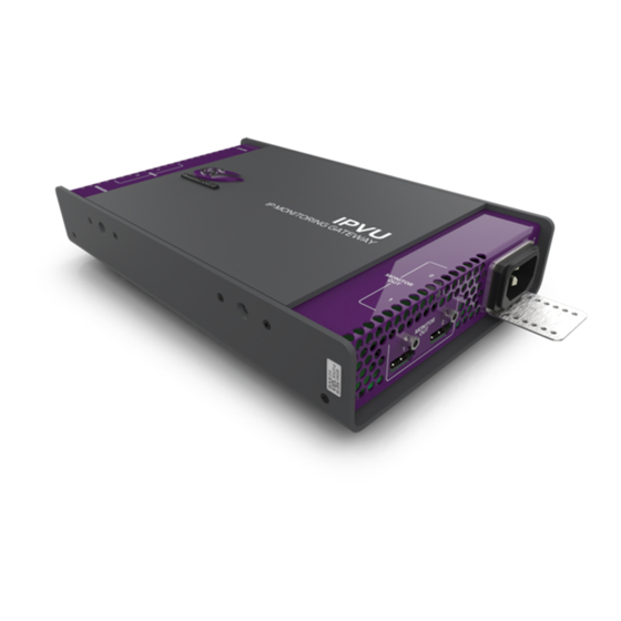
Introduction Overview The IPVU is a compact dual channel IP to HDMI converter that’s perfect for displaying IP sources and multiviewer’s IP outputs on HD and UHD monitors with an HDMI input. The IPVU can be installed on a rack shelf or mounted behind the display, and provides the missing link to view any IP source, or to connect an IP multiviewer’s output to its display. -
Page 18: Benefits
Introduction Benefits Benefits • Dual channel to optimize switch port bandwidth usage. • Low processing latency for critical monitoring applications. • In-band or out-of-band control for more flexibility. • Clean switch between two IP sources with no video loss (make before break or freeze frame). -
Page 19: Block Diagram
IPVU Installation Guide Block Diagram Video Formatting HDMI 10 / 25 Gb 2.0b Ethernet Audio IP Decapsulation Monitor Output 1 Formatting ST 2110 / ST 2022‐6* MEDIA 1 (SFP28) ST 2022‐7 Redundancy ST 2059 PTP Stream Selection Video (break/make) Formatting HDMI 2.0b 10 / 25 Gb Audio Ethernet Formatting Monitor Output 2 In‐band* MEDIA 2 (SFP28) Control Out‐of‐band Control Control Status Configuration MANAGEMENT Internal power supply (RJ45) -
Page 20: Supported Media Port Sfp28 Cartridges
Introduction Supported MEDIA Port SFP28 Cartridges Supplied with the IPVU Supplied HD and HD/3G, and Quantity Description 3G video UHD video IPVU (IPVU-UHD). Power cord with attached IEC 60320 C13 connector. Supported MEDIA Port SFP28 Cartridges One or two SFP28 cartridges are required (extra). These are shipped as a separate order. See also Video Resolution and SFP Cartridge Bandwidth and Quantity Requirements, on... -
Page 21: Required Materials
IPVU Installation Guide Required Materials Field-supplied materials that must be provided. Required Quantity Description 1 or 2 Fiber optic cable to connect between the IPVU and network switch. The ends must be terminated with the appropriate connectors. 1 or 2 Standard monitor cable with connectors at each end: •... -
Page 22: Field-Replaceable Units
Introduction Field-Replaceable Units Field-Replaceable Units The following units are field-replaceable for maintenance purposes. FRU part number Description IPVU HD and 3G video. IPVU-UHD HD/3G, and UHD video. IPVU Mechanical Dimensions The following diagram shows the IPVU’s physical dimensions. 11.41 [290] <-0.66 1.91 [49] 9.00 [229]... -
Page 23: Ipvu-Tray Mechanical Dimensions
IPVU Installation Guide IPVU-TRAY Mechanical Dimensions The following diagram shows the IPVU-TRAY’s physical dimensions. Top View 14.0 [353.8] Side View 19 Inch Rack: 18.95 [481.3] 18.312 [465.12] 1 RU: 1.72 [43.6] Front View inches [millimeters] Fig. 1-3: IPVU-TRAY dimensions... -
Page 24: Ipvu-Mounting-Kit Mechanical Dimensions
Introduction IPVU-MOUNTING-KIT Mechanical Dimensions IPVU-MOUNTING-KIT Mechanical Dimensions The following diagrams shows the IPVU-MOUNTING-KIT’s physical dimensions. Mounting on a Wall or Under a Table Top The bracket of the IPVU-MOUNTING-KIT can be attached to a hard surface with screw fasteners. 6.69 [76.2] [170] [53.4]... -
Page 25: Mounting With A Wall-Mounted Monitor
IPVU Installation Guide Mounting with a Wall-Mounted Monitor The bracket of the IPVU-MOUNTING-KIT can be attached to the wall mount support of a monitor that is 32 inches diagonal or larger. 6.69 [170] Top View End View 10.08 [256.2] 1.69 [42.9] 2.77 [70.5] 5.62 [142.7] 2.38... -
Page 26: Mounting Onto A Vesa 75Mm Or 100Mm Stand-Mounted Monitor
Introduction Mounting onto a VESA 75mm or 100mm Stand-Mounted Monitor Mounting onto a VESA 75mm or 100mm Stand-Mounted Monitor The bracket of the IPVU-MOUNTING-KIT can be attached to a VESA 75mm or 100mm monitor stand of a monitor that is 31 inches or smaller. 4.5 [114.3] VESA VESA... -
Page 27: Connections And Cabling
Connections and Cabling Cabling Diagrams The IPVU is intended to be used in close proximity to the monitor, using a 6 foot or shorter cable between the IPVU and the monitor. The following figure shows the typical connections for an IPVU. AC Outlet Multimode MEDIA 1... - Page 28 Connections and Cabling Cabling to Support SMPTE 2022-7 with an IPVU Media Network Switch ‘Red’ Media Red IPVU A MEDIA 1 Kahuna Kaleido-IP A MEDIA 2 IPVU B Kaleido-IP B Camera MEDIA 1 MEDIA 2 Media Blue Media Network Switch ‘Blue’ Fig.
-
Page 29: Electrical Connections, Reset Pushbutton, And Status Indicators
IPVU Installation Guide • For the IPVU, in Rollcall’s Spigot panel, Primary / Secondary tab, make sure to change the Flow Type from None to 2110-20. See Spigots, on page 67. Electrical Connections, Reset Pushbutton, and Status Indicators The following diagram shows the IPVU’s electrical connections, reset pushbutton, and the location of status indicators. -
Page 30: Sfp Cartridge 1 & 2 Status Indicators
Connections and Cabling Reset Pushbutton SFP Cartridge 1 & 2 Status Indicators This shows the health of the media Ethernet link to the switch. Status Indicator Color Interpretation SFP cartridge not installed. Blue 25G link up. Flashing blue 25G link down. Green 10G link up. - Page 31 IPVU Installation Guide Cable assemblies with regular, non-locking connectors can equally be used for the monitor outputs. Screw-Lock Monitor cable assembly Plug Fig. 2-5: Typical screw-lock connector with a Type A male connector...
- Page 32 Connections and Cabling Locking Monitor Outputs...
-
Page 33: Installation
Installation Fiber Optic Handling CAUTION Never assume a fiber is dark. Never look directly into the end of a fiber cable. All employees in the area must wear laser safety glasses with side shields. Installing connectors on a fiber requires special handling procedures. Read and follow the fiber and connector manufacturer’s instructions. -
Page 34: Mounting Options
Installation Mounting Options Mounting Options Optional mounting kits are available to mount the IPVU as follows. Mounting Method Required mounting kit Description 1 RU 19” Rack IPVU-TRAY 19” rack mount shelf for 1 RU rack Installing IPVUs in a 19” Rack, installation of up to three IPVUs. -
Page 35: Mounting An Ipvu On A Wall Or Under A Table Top
IPVU Installation Guide To install the IPVU-TRAY mounting kit in a 19” rack 1 Install the IPVU-TRAY shelf into the rack. Use the four supplied rack screws to attach the shelf to the rack. 2 From the rear of the rack, pull through the power and monitor cables required for each space in the shelf where each IPVU is to be installed. - Page 36 Installation Mounting an IPVU on a Wall or Under a Table Top When mounting the IPVU on a wall behind a monitor, operate the monitor for 30 minutes and then feel the rear housing with your hand. Avoid mounting the IPVU behind the monitor in areas where the monitor is warm to the touch and above these warm spots.
- Page 37 IPVU Installation Guide The l IPVU-MOUNTING-KIT’s screw hole locations are shown below. Screw Hole Locations 4 IPVU-MOUNTING-KIT Bracket Front View Fig. 3-5: Screw hole locations for wall mounting the IPVU-MOUNTING-KIT To install the IPVU-MOUNTING-KIT on a wall or under a table top 1 Identify the screw hole locations on the IPVU-MOUNTING-KIT bracket.
-
Page 38: Installing The Ipvu Into The Ipvu-Mounting-Kit
Installation Installing the IPVU into the IPVU-MOUNTING-KIT Installing the IPVU into the IPVU-MOUNTING-KIT The IPVU is attached to the IPVU-MOUNTING-KIT with two thumbscrews as shown below. Side View IPVU Threaded Mounting Holes IPVU IPVU-MOUNTING-KIT Bracket Thumbscrews End View Fig. -
Page 39: Mounting An Ipvu With A Wall-Mounted Monitor
IPVU Installation Guide Mounting an IPVU with a Wall-Mounted Monitor The IPVU-MOUNTING-KIT can be used with a wall mounted monitor that is 32 inches diagonal or larger. IPVU IPVU-MOUNTING-KIT Standard Wall-Mount Bracket Rear of Monitor (looking into room) NOTE: The wall has been removed for clarity Fig. - Page 40 Installation Mounting an IPVU with a Wall-Mounted Monitor 1 Use two screws to assemble the IPVU-MOUNTING-KIT as shown below. Set the IPVU’s mounting orientation; see IPVU Mounting Orientation for a Wall-Mounted Monitor, on page 42. IPVU-MOUNTING-KIT Clamp IPVU Side View IPVU-MOUNTING-KIT Components Note: Set the Mounting Orientation Fig.
- Page 41 IPVU Installation Guide 5 Slide the IPVU-MOUNTING-KIT down between the wall-mount bracket and the monitor (as shown in Figure 3-12) until the lower IPVU-MOUNTING-KIT slot aligns with the Wall- Mount Bracket’s screw location. Using the lower IPVU-MOUNTING-KIT slot provides better leverage to support the IPVU’s weight. Always use the lower IPVU- MOUNTING-KIT...
-
Page 42: Ipvu Mounting Orientation For A Wall-Mounted Monitor
Installation IPVU Mounting Orientation for a Wall-Mounted Monitor 7 Snug the IPVU-MOUNTING-KIT’s clamp up to the wall-mount bracket’s arm and tighten the thumbscrew to further support the IPVU. 8 Install the IPVU into the IPVU-MOUNTING-KIT bracket. See Installing the IPVU into the IPVU-MOUNTING-KIT, on page 38. -
Page 43: Mounting An Ipvu Onto A Vesa 75Mm Or 100Mm Stand-Mounted Monitor
IPVU Installation Guide Mounting an IPVU onto a VESA 75mm or 100mm Stand-Mounted Monitor The IPVU-MOUNTING-KIT can be used with a VESA 75mm or 100mm stand-mounted monitor that is 31 inches or smaller. Fig. 3-14: IPVU-MOUNTING-KIT for VESA stand-mounted monitors When mounting the IPVU behind a monitor, operate the monitor for 30 minutes and then feel the rear housing with your hand. - Page 44 Installation Mounting an IPVU onto a VESA 75mm or 100mm Stand-Mounted Monitor To install an IPVU with a VESA-Mount Monitor This procedure assumes that the monitor has already been attached to a VESA mount monitor stand. 1 Use two screws to assemble the IPVU-MOUNTING-KIT as shown below. Set the IPVU’s mounting orientation;...
- Page 45 IPVU Installation Guide 3 Sandwich the IPVU-MOUNTING-KIT between the monitor and the VESA mount monitor stand. IPVU-MOUNTING-KIT Bracket IPVU End View Fig. 3-17: Attaching the IPVU-MOUNTING-KIT to the VESA mount monitor stand 4 Replace the four screws that attach the monitor to the VESA mount monitor stand. 5 Install the IPVU into the IPVU-MOUNTING-KIT bracket.
-
Page 46: Ipvu Mounting Orientation For A Stand-Mounted Monitor
Installation IPVU Mounting Orientation for a Stand-Mounted Monitor IPVU Mounting Orientation for a Stand-Mounted Monitor The IPVU can be attached to the IPVU-MOUNTING-KIT bracket in either of two Perpendicular orientations. This choice is made during the assembly of the IPVU-MOUNTING-KIT bracket by choosing the appropriate set of attachment points, as shown below. -
Page 47: Securing The Ipvu-Mounting-Kit With Fastener Points
IPVU Installation Guide Securing the IPVU-MOUNTING-KIT with Fastener Points If none of the previous IPVU-MOUNTING-KIT mounting methods work, you can use the IPVU-MOUNTING-KIT’s fastener points to secure the IPVU in place with nylon cable ties. These same fastener points can also be used to secure cables in place for any installation where the IPVU-MOUNTING-KIT is used (see Figure 3-20). -
Page 48: Connecting The Ipvu
Installation Connecting the IPVU Connecting the IPVU Use field-supplied OM4 Multimode Fiber (MMF) single fiber optical cable fitted with SC connectors with the IPVU. For an installation overview, see Cabling Diagrams, on page 27. Proceed as follows: 1 Insert the SFP cartridge(s) into the IPVU: see Installing the SFP Output Module, on page 95. - Page 49 IPVU Installation Guide 4 Connect a standard monitor cable with type A connectors to the IPVU’s MONITOR OUT 1 port. Then connect the other end of the monitor cable to the Monitor’s Digital Input. If a second monitor is to be used, connect it to the IPVU’s MONITOR OUT 2 port. <6’...
- Page 50 Installation Connecting the IPVU 7 Prevent power cord pull-out by adjusting the position of the AC power cord retainer clip so that the power cord plug is firmly held into the socket. Then clip it onto the power cord. Test it by gently pulling on the power cord’s plug (do not pull on the cable). AC Power Cord Plug Retainer Clip...
-
Page 51: Ipvu Commissioning And Configuration
IPVU Commissioning and Configuration IPVU Commissioning and Configuration is done with RollCall software. Factory Default IP Address and Network Port Usage The factory default management IP address for the IPVU is 192.168.3.31. To set the IP configuration, see Ethernet Gb, on page 79. Certain ports must be open on the management network. -
Page 52: Navigating Pages In The Rollcall Template
IPVU Commissioning and Configuration Navigating Pages in the RollCall Template Navigating Pages in the RollCall Template The RollCall template has a number of pages, each of which can be selected from the drop- down list at the top left of the display area. Right-clicking anywhere on the pages will also open a page view list, allowing quick access to any of the pages. -
Page 53: Setting Values
IPVU Installation Guide Setting Values Many of the settings within the templates have values, either alpha or numeric. When setting a value in a field, the value, whether text or a number, must be set by pressing the Enter key, or clicking the Save Value button. -
Page 54: Ipvu
IPVU Commissioning and Configuration IPVU IPVU The IPVU page allows basic parameters to be set. Fig. 4-3: IPVU Configuration Page The following facilities are available from this page: Option Operation Frame Rate Set the system frame rate frequency. Frame Rate Consistency Show if there is a missmatch between the incoming video stream and the system frame rate. -
Page 55: Configuration
IPVU Installation Guide Configuration The Configuration page allows basic IPVU parameters to be set. Fig. 4-4: Configuration Page The following facilities are available from this page: Option Operation Genlock Select Genlock type: • Network - click to select PTP. • Freerun - click to allow free running. Status The current genlock status: NO LOCK / LOCKED / Freerun. -
Page 56: Time Sync Configuration
IPVU Commissioning and Configuration Time Sync Configuration Option Operation Domain RollCall+ uses domains to partition a network; only nodes on the same domain can communicate with one another. A domain is uniquely identified with a number and a friendly name/alias. Set an ID as required, then press Take to confirm the change. - Page 57 IPVU Installation Guide The following facilities are available from this page: Option Operation Time Sync Mode Click a radio button to select the required mode. Note that the PTP options require a grandmaster clock to be present in the system. NTP Configuration To add an NTP server, enter the server’s IP address in to the New field.
-
Page 58: Status
IPVU Commissioning and Configuration Status Status When the displays important system status Show Status checkbox is set (see above), this information in a single convenient panel. Fig. 4-6: Time Sync Status Option Operation Reset Counters Clear the accumulated data. Next Interface Cycle through the available Ethernet interface. -
Page 59: Histogram
IPVU Installation Guide Histogram When the located to the right of the Status panel, Show Status checkbox is set (see above), the Histogram provides a graphical representation of the distribution of differences between the card's clock and the PTP grandmaster clock. Every time the clock difference is recalculated, the relevant bar is incremented. -
Page 60: Counters
IPVU Commissioning and Configuration Counters The following options are available for each spigot: Option Operation TPG Enable Display a test pattern at MONITOR OUT 1 / 2. represents the IPVU’s MONITOR OUT 1 connection and Spigot 1 Spigot 5 represents the IPVU’s MONITOR OUT 2 connection. See Electrical Connections, Reset Pushbutton, and Status Indicators on page 29 Caption... -
Page 61: Fec
IPVU Installation Guide The FEC page allows FEC Clause 74 to be selected and FEC logging to be activated, if required. FEC stats are also available. Fig. 4-10: FEC Page SFP 1 represents the IPVU’s MEDIA 1 connection and SFP 2 represents the IPVU’s MEDIA 2 connection. -
Page 62: Ethernet Pages 1 And 2
IPVU Commissioning and Configuration Ethernet Pages 1 and 2 Log Field Description FEC CORRECTED Number of corrected errors for FEC N. ERRORS FEC UNCORRECTED Number of uncorrected errors for FEC N. ERRORS Where N is the SFP number Ethernet Pages 1 and 2 Note: Ethernet pages 1 &... -
Page 63: The Ethernet Pane
IPVU Installation Guide The Ethernet Pane The Ethernet pane displays details of the currently selected network interface, and allows a static IP address to be defined. Enter information as required, then click S to save. New settings are applied when Restart is clicked. Clear Link Change Count If the state of the Ethernet link changes, the Link Change Count and Link Change Time fields are updated. -
Page 64: Ethernet Rtp Receiver Video Stats
IPVU Commissioning and Configuration Ethernet RTP Receiver Video Stats Ethernet RTP Receiver Video Stats The Ethernet RTP Receiver Video Stats page displays information on the data received via RTP on each Ethernet input. Units are megabits per second. Click Enable Stats to display values;... -
Page 65: Ethernet Rtp Receiver Audio Stats
IPVU Installation Guide Ethernet RTP Receiver Audio Stats The Ethernet RTP Receiver Audio Stats page displays information on the data received via RTP on each Ethernet input. Units are megabits per second. Click Enable Stats to display values; click Clear All RTP Counts to zero RTP Discontinuity counters for each Ethernet input. -
Page 66: Audio V Fade
IPVU Commissioning and Configuration Audio V Fade Audio V Fade The Audio V Fade template configures an audio V-fade for each video input IP stream (for example, at receiving, destination spigots). When the video input switches to another, an audio V-fade can be used to reduced audio disturbances at the switch-over. Fig. -
Page 67: Spigots
IPVU Installation Guide The following options are available. Enable check boxes to activate log fields as required. Log Field Description On Input Loss Freeze: Select to freeze video. Black: Select to use video black. Spigots A separate page is provided for each of the active output spigots. Fig. -
Page 68: Spigot Pane
IPVU Commissioning and Configuration Spigot Pane Spigot Pane The Spigot pane provides basic monitoring for the selected Spigot. Click Take to apply any changes made. Fig. 4-18: Output Spigot Pane The Spigot pane details: • Spigot direction; • Current status; •... -
Page 69: Flow Panes (Primary And Secondary)
IPVU Installation Guide Make/Break Mode Specifies how changes to an output’s destination will be made. Make before Break causes the new destination to buffer data before connection to the previous destination is broken; this results in a smoother transition, but requires more bandwidth. Break before Make simply swaps the output’s destination without buffering. -
Page 70: System Status
IPVU Commissioning and Configuration System Status System Status Each status page comprises two columns: the parameter and its corresponding value. Fig. 4-20: System Status Page The following status information is available. Status Description Serial Number Reports the IPVU’s serial number. OS Version Reports the operating system name and version. - Page 71 IPVU Installation Guide Status Description Time Sync Mode Valid values are: • Free running: Card is using its own clock with no reference to any other source. • PTP Multicast: Card is synchronizing to a PTP grandmaster clock using multicast network messages. •...
-
Page 72: Network Status
IPVU Commissioning and Configuration Network Status Status Description Time Sync Last Lock Time when the IPVU last changed from not locked to locked. Ideally this will be a few seconds after the IPVU has powered up. This allows the user to confirm which clock the IPVU has synchronized Time Sync Reports the number of times the card has synchronized since it was Synchronisations... - Page 73 IPVU Installation Guide The following status information is available. Ethernet 1 represents the IPVU’s MEDIA 1 connection and Ethernet 2 represents the IPVU’s MEDIA 2 connection. See Electrical Connections, Reset Pushbutton, and Status Indicators, on page 29. Status Description Ethernet n Name Displays the Ethernet port name.
-
Page 74: Card Diagnostics
IPVU Commissioning and Configuration Card Diagnostics Status Description Ethernet n Switch Port ID Reports Port ID of the network switch the IPVU is connected to. Ethernet n Switch Port Reports name of the VLAN that the IPVU is connected to. VLAN Card Diagnostics Each status page comprises two columns: the parameter and its corresponding value. -
Page 75: Sfp Status
IPVU Installation Guide SFP Status Each status page comprises two columns: the parameter and its corresponding value. Fig. 4-23: Logging - SFP Page... - Page 76 IPVU Commissioning and Configuration SFP Status The following options are available. Enable check boxes to activate log fields as required. Status Description Fitted Displays presence of SFP. Valid values are: • OK • Missing Status Displays status reported by the SFP. Valid values are: SFPs •...
-
Page 77: Setup
IPVU Installation Guide Status Description Tx Bias n Displays bias level in mA. Tx Power n Displays transmit power level in dBm. Tx Power State n Displays transmit power level. Valid values are: • OK • WARN:Low - Low, but in tolerance. •... -
Page 78: Restart
IPVU Commissioning and Configuration Restart The Product pane displays technical information on the IPVU. You may be asked for these details by Grass Valley support if you need technical assistance. See Grass Valley Technical Support, on page 98. Item Description Product Name of the IPVU module. -
Page 79: Ethernet Gb
IPVU Installation Guide Ethernet Gb The Ethernet Gb page shows details and status of the IPVU’s MANAGEMENT Ethernet connector (see Electrical Connections, Reset Pushbutton, and Status Indicators, on page 29). The IPVU defaults to use of DHCP, but this can be overridden and a static IP address specified if required. -
Page 80: Interop
IPVU Commissioning and Configuration Interop Interop The Interop page allows certain parameters to be changed in order to improve interoperability with third-party equipment. Fig. 4-26: Interop Page The following facilities are available from this page: Option Operation Stream Synchronization Audio: Controls •... -
Page 81: Sfp Configuration
IPVU Installation Guide SFP Configuration The SFP Configuration page allows various SFP parameters to be adjusted, if required. Fig. 4-27: SFP Configuration Page The majority of SFPs will operate correctly with IPVU without any need for adjustment. Some, however, may need to have IPVU parameters set a little differently. If difficulties are encountered with an SFP not working as expected, follow these instructions: 1 Select the appropriate SFP type from the SFP Database List, and click Take. - Page 82 IPVU Commissioning and Configuration SFP Configuration 3 When a working configuration is found, the parameter values can be saved by clicking S beside each field.
-
Page 83: Maintenance & Troubleshooting
Maintenance & Troubleshooting This chapter shows you the various maintenance operations and corrective actions that maybe required to be performed during system commissioning and over the IPVU’s lifetime. Maintenance Power Cycling an IPVU When power cycling the IPVU, disconnect the power from the IPVU for at least 5 seconds before reconnecting power again. -
Page 84: Upgrading The Ipvu's Firmware
Maintenance & Troubleshooting Upgrading the IPVU’s Firmware Upgrading the IPVU’s Firmware The following is required to proceed: • A Microsoft Windows PC that: • has Internet connectivity. • has network connectivity with the IPVU. • has RollCall software installed. • IPVU firmware files. A firmware upgrade package is supplied by Grass Valley Support and comprises a set of data and installer files. - Page 85 IPVU Installation Guide 3 Click the Import Upgrade Package button. Fig. 5-4: Select Upgrade Package 4 Browse to the folder containing the upgrade package. 5 Select the upgrade package and click OK. When the package has been imported, it is added to the list of available upgrades, and units may be upgraded accordingly.
- Page 86 Maintenance & Troubleshooting Upgrading the IPVU’s Firmware 2 Click on Unit Upgrade from the unit menu. The Unit Upgrade dialog displays. Fig. 5-6: Unit Upgrade Dialog The following elements and options are available: • Unit - This panel displays the unit address, serial number, and hardware version (if available).
- Page 87 IPVU Installation Guide must be imported using the Import new Upgrades function available from the main toolbar. • Release Notes - If release notes are available, clicking this button displays them. If release notes are not available, this button is not displayed. •...
-
Page 88: Troubleshooting
Maintenance & Troubleshooting Troubleshooting 1 In RollCall, right-click IPVU and select Delete Cache. Fig. 5-7: IPVU Menu 2 Close and restart RollCall. Troubleshooting Following a methodical process of elimination, try the following steps. 1 Are you using the latest IPVU firmware? To upgrade an IPVU’s firmware, see Firmware Upgrade, on page 51. -
Page 89: Keep Fiber Connections Clean
IPVU Installation Guide Further troubleshooting. Problem Possible solutions… Screen is not displayed, but Make sure the monitor supports the resolution used by the status LED is green IPVU. If your monitor supports it, turn the automatic resolution detection on. Make sure the display is turned on. Test the monitor by feeding it a signal from another source. - Page 90 Maintenance & Troubleshooting Keep Fiber Connections Clean There are a variety of cleaning solutions available to help the fiber user maintain good fiber network performance. For best results, it should be possible for the user to perform a visual inspection of the fiber ends to verify cleanliness. Grass Valley strongly urges all users to select a cleaning method that meets their needs, and to use it rigorously and consistently.
-
Page 91: Specifications
Specifications Status LEDs Electrical Connections, Reset Pushbutton, and Status Indicators, on page 29. Inputs & Outputs MEDIA 1 & 2 Ports 2 SFP28 Ethernet cartridge slots Physical Supported SFP28 Supported MEDIA Port SFP28 Cartridges, on page 20 cartridges Speed 10 or 25 GbE Ethernet IEEE 802.3-2008 10 GigE... -
Page 92: Monitor Out
Specifications MONITOR OUT Audio Single stream per MEDIA output connection Up to 32 channels, only the first 8 are available for use per MEDIA output connection, 125us to 4ms Processing delay < 1 frame a. Available on demand MONITOR OUT 2 ... -
Page 93: Status Indicators
IPVU Installation Guide Status Indicators Status Indicator Interpretation, on page 29. Environmental Weight IPVU 2.0lb (930g) Dimensions IPVU Mechanical Dimensions, on page 22 Cooling Mounting Requirements, on page 33 Temperature Range Operating 32 to 104°F (0 to 40°C) Storage -40 to 185°F (-40 to 85°C) User safety When an open fiber condition is detected, the lasers are turned off. - Page 94 Specifications Compliance...
-
Page 95: Appendix A Installing The Sfp Output Module
Installing the SFP Output Module Introduction Installing and removing the SFP output interface cartridge requires special care. This annex describes the process. Rear panels incorporate one or two SFP interface(s). The interface consists of two parts: • A socket on the rear panel into which an SFP interface module is plugged •... -
Page 96: Connecting The Fiber Optic Cables
Installing the SFP Output Module Connecting the fiber optic cables 3 Slide the module straight into the socket, and push gently until it clicks into position. Connecting the fiber optic cables 1 Remove the dust plug from the SFP module if present 2 Verify that the exposed end of the optical fiber in the LC connector is clean •... - Page 97 KMX-4911 / KMX-4921 Installation & Service Manual Bale Clasp 2 Grasp the SFP module between your thumb and forefinger, and pull it straight out of the slot. • Do NOT pull on the bale clasp lever to remove the module, as it is easily damaged. •...
- Page 98 Contact Us Grass Valley Technical Support For technical assistance, contact our international support center, at 1-800-547-8949 (US and Canada) or +1 530 478 4148. To obtain a local phone number for the support center nearest you, please consult the Contact Us section of Grass Valley’s website ( www.grassvalley.com An online form for e-mail contact is also available from the website.
Need help?
Do you have a question about the Grass Valley IPVU and is the answer not in the manual?
Questions and answers