Table of Contents
Advertisement
Quick Links
Advertisement
Table of Contents

Related Manuals for Gates Underwater Products DEEP KOMODO


Summary of Contents for Gates Underwater Products DEEP KOMODO
-
Page 1: Setup, Use, And Care Guide
DEEP KOMODO Housing Setup, Use, and Care Guide... - Page 2 Cautions Page 2 Copyright 2020, Gates Underwater Products, Inc. This manual and current revision is available in 8.5 x 11 size and full color at http://www.gateshousings.com/documentation.html Gates Underwater Products, Inc. 13685 Stowe Drive Poway, California 92064 USA Phone: 858.391.0052 outside the U.S.
-
Page 3: Table Of Contents
Required Equipment ..............6 Cautions ..................7 DEEP KOMODO Setup .............. 9 DK Housing Overview ..............9 DEEP KOMODO Housing Preparation ........11 Preparing the KOMODO Camera ..........16 KOMODO Cables Connect ............20 Camera / Camera Tray Install ........... 21 Main Shell Mating .............. -
Page 4: Introducing Deep Komodo
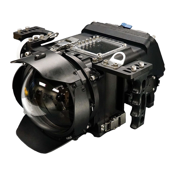
Page 4 Introducing DEEP KOMODO Congratulations on owning a new Gates product: the DEEP KOMODO (DK) housing. You’ve selected a product that will provide years of value and reliable service. We designed DK specifically as a professional action underwater rig for cinema, natural history, surf and research applications. -
Page 5: Unpacking Deep Komodo
Cautions Page 5 Unpacking DEEP KOMODO After you remove DK from its shipping container, carefully inspect it for missing parts or damage that may have occurred during shipment. If you discover any discrepancies, contact Gates or your dealer immediately for assistance. -
Page 6: Required Equipment
Cautions Page 6 Required Equipment The required camera and accessory equipment for DK is: ✓ • • ATOMOS SHINOBI SDI SMALLHD 503 Ultrabright ✓ Camera • RED DIGITAL CINEMA KOMODO. ✓ Battery (x2) • Sony NP-F970 • HEDBOX RP-NPF970 • Equivalent L-Series battery of dimensions: ▪... -
Page 7: 1: Cautions
Cautions Page 7 1: Cautions ✓ SEAL CHECK VACUUM. In a later part of this manual, Seal Check Lite will be introduced for verifying seal integrity before diving. You will learn that the vacuum draw on DK should be about 100 millibars. This is enough to verify seal integrity. - Page 8 Cautions Page 8 ✓ CAMERA TRANSPORT INSIDE HOUSING. You can transport a securely mounted camera inside DK IF the system is in your possession and without abusive handling. DO NOT transport a camera inside DK for shipping or checked baggage as forceful and abusive handling can cause damage to both camera and housing.
-
Page 9: 2: Deep Komodo Setup
DEEP KOMODO Setup Page 9 2: DEEP KOMODO Setup DK Housing Overview DK has many features with which you will become familiar. KOMODO display view window with full pushbutton controls. Adjustable Handle Grips. Mechanical lens control. Map to Focus / Iris / Zoom. - Page 10 DEEP KOMODO Setup Page 10 Angled, rear view LCD. Gates COMMAND / CONTROL Module. Direct Iris, ISO and Shutter authority. 4 Assignables and Status Display. LCD Touchscreen Controls (SHINOBI SDI shown). Bulkhead Adapter (x2) for optional surface control / Master Power Switch.
-
Page 11: Deep Komodo Housing Preparation
DEEP KOMODO Setup Page 11 DEEP KOMODO Housing Preparation ✓ Handle Grips Install. Four screws secure the Handle Grips to DK. You can locate the Handle Grips in several different positions forward / aft on the housing. ✓ Port Removal. Disengage the Port by rotating 90 degrees in the direction shown. - Page 12 DEEP KOMODO Setup Page 12 ✓ Stackable Port Ring (SPR). Remove the SPR’s one at a time or as a group. The lock pin is shown below in the locked and release position. Lock position Release position. ✓ With the SPR’s unlocked, rotate 90 degrees and separate.
- Page 13 DEEP KOMODO Setup Page 13 ✓ Shell Latches. Release 3 locking latches. One on top, 2 on the either side. ✓ Separate the two main shells. They will slide apart. Release 3 Latches.
- Page 14 DEEP KOMODO Setup Page 14 ✓ Release Remove Camera Tray. Release the lock arm counter-clockwise as shown, and the camera tray will slide away to the rear. Lock arm release.
- Page 15 DEEP KOMODO Setup Page 15 ✓ Seperate LCD Front Shell. Use the 3/16 ball driver in the Took Kit to loosen 4 corner screws, as shown. (These are captive screws and do not remove.)
-
Page 16: Preparing The Komodo Camera
DEEP KOMODO Setup Page 16 Preparing the KOMODO Camera ✓ GCC Communications. KOMODO camera requires specific settings within the menu for operation with the COMMAND / CONTROL Module. BAUD RATE. MENU → COMMUNICATION → SERIAL → BAUD → 1000000 IP ADDRESS. MENU → COMMUNICATION → SERIAL → IP ADDRESS →... - Page 17 A lens adapter (e.g. RF to EF, RF to PL) is OK. ✓ Power Switch. KOMODO power switch must be in the ‘on’ position to auto-boot in the DEEP KOMODO system. Turn on KOMODO power switch. If not using RED CONTROL app, disable WIFI.
- Page 18 * With the LCD on, navigate to the ‘page’ you wish to use in DEEP KOMODO. * Turn off the LCD via the POWER button. Then power back on. This ‘sets’ this...
- Page 19 DEEP KOMODO Setup Page 19 Camera / Battery Installation Details of the RED camera install are shown in the following images. ✓ Mate camera to Camera Tray, then tighten the wing screw to secure in place. ✓ Install Batteries. Mate and lock batteries into place as shown.
-
Page 20: Komodo Cables Connect
DEEP KOMODO Setup Page 20 KOMODO Cables Connect At this point several connections between KOMODO and Camera Tray are required. ✓ Power. The power cable will connect on the right rear PWR input on KOMODO. ✓ Communications. Similarly, the communications cable will connect to lower left rear of KOMODO, the EXT port. -
Page 21: Camera / Camera Tray Install
DEEP KOMODO Setup Page 21 Camera / Camera Tray Install Next, mount KOMODO / Camera Tray package into the DEEP KOMODO front shell. ✓ Align the Camera Tray with the dovetail receiver on the front shell. Slide the camera into the housing until it stops. -
Page 22: Main Shell Mating
DEEP KOMODO Setup Page 22 Main Shell Mating Mating the main shell parts is straightforward. ✓ Align the Front Shell / Camera Tray with the Rear Shell, as shown. Gently slide the shells together until they mate fully. IF YOU ENCOUNTER AN OBSTRUCTION – STOP – IDENTIFY THE PROBLEM AND PROCEED AGAIN. -
Page 23: Install Lcd & Lcd Front Shell
DEEP KOMODO Setup Page 23 Install LCD & LCD Front Shell First, make the following cable connections inside the housing. Looking in through the rear shell: ✓ GCC. Just inside the rear shell opening you will find a cable leading from the GCC. - Page 24 DEEP KOMODO Setup Page 24 ✓ LCD Power to LCD as shown in RED. ✓ LCD SDI to LCD SDI Input, shown in GOLD. ✓ Place the LCD into the guides, as shown. ✓ Place and secure the LCD Front Shell.
-
Page 25: Cable Management
DEEP KOMODO Setup Page 25 Cable Management Note that the DK SDI and LCD Power Cables are secured together with a flexible cable wrap. We recommend you wrap the GCC Cable into this bundle for good cable management inside the housing. -
Page 26: Mount Lens
DEEP KOMODO Setup Page 26 Mount Lens If your lens requires Flex Gears, install those first and then mount the lens to the camera. -
Page 27: Lens Gear Drives (Lgd's)
DEEP KOMODO Setup Page 27 Lens Gear Drives (LGD’s) ✓ General Notes. This section addresses the installation of two Lens Gear Drives (LGD’s) in DK. This is relatively straightforward, using only two parts for each lens control: a drive shaft and drive gear. - Page 28 DEEP KOMODO Setup Page 28 Pro Action Shown 1. Loosen this screw on each LGD to allow the Lens Gear Drives to pivot and mate with the Flex Gears. 2. Pivot the LGD’s to mate with the Flex Gear. Ensure a good gear mesh.
-
Page 29: Lens Gear Drive (Lgd) Size Reference
DEEP KOMODO Setup Page 29 Lens Gear Drive (LGD) Size Reference DK includes several size LGD’s to accommodate different lens sizes. Below is a reference. Focus Gears P/N 3000-94-242 P/N 3000-94-228 Iris and Zoom Gears P/N 3000-94-229 P/N 3000-94-233 P/N 3000-94-246 P/N 3000-94-239 LGD’s designed for... -
Page 30: Functional System Check
DEEP KOMODO Setup Page 30 Functional System Check Before the next step – assembling Port Rings and Port – this is a good time to do a full system check. Activate the Master System Power switch and verify all components operational (see next section on controls for location of Master System Power and LCD Power Switch (if installed). -
Page 31: Red Control - A Note About Wireless Camera Control
DEEP KOMODO Setup Page 31 RED CONTROL – a note about wireless camera control A powerful tool for DK is wireless control of all camera functions. The official RED CONTROL app enables such control – even at close proximity through the DK housing shell. -
Page 32: Configure Spr's And Port
DEEP KOMODO Setup Page 32 Configure SPR’s and Port Stackable Port Rings are a flexible and convenient way to support many different lenses. They can be stacked in many combinations to support virtually any lens. Stackable Port Rings – SPR’s – are a simple 1/4 turn bayonet mount system to support any lens. - Page 33 DEEP KOMODO Setup Page 33 ✓ A Flat Port is used commonly for macro lenses, and also for medium to long focal length lenses. The focal range that works best starts at approximately 20-35 mm. Referring to the image, setup the SPR’s to extend just past the end of the lens. Keep the entire SPR stack as short as possible while preventing interference with the port.
- Page 34 DEEP KOMODO Setup Page 34 ✓ A Dome Port is used commonly with wide angle and fisheye lenses, typically 8mm at the shortest (35mm equivalent) to about 20-35mm. Referring to the image, setup the SPR’s so the end of the lens – either the lens body or glass element –...
-
Page 35: Mount Stackable Port Rings (Spr's) And Port
DEEP KOMODO Setup Page 35 Mount Stackable Port Rings (SPR’s) and Port ✓ SPR’s are assembled in any order on the housing. Place the lock pin on the first SPR in the ‘lock’ position. ✓ Lubricate O-Rings as necessary for smooth, easy rotation. - Page 36 DEEP KOMODO Setup Page 36 ✓ When finished mounting SPR’s, mount a Port to the SPR’s in the same manner, mating 90 degrees and rotating counter clockwise when viewing from the rear of the housing. Mate the Port 90 degrees CW from it’s normal position, then rotate 90...
-
Page 37: Changing The Port Base
DEEP KOMODO Setup Page 37 Changing the Port Base Gates larger port series – the 80 series – can be used with DK. The 80 series port system includes both SP80-8 in and SP80-10 in spherical diameter dome ports. This can be useful in certain applications where the benefits of a larger dome are realized. - Page 38 DEEP KOMODO Setup Page 38 Install the taller feet.
-
Page 39: Installing The 60-80 Spr Adapter
DEEP KOMODO Setup Page 39 Installing the 60-80 SPR Adapter DK allows for using 80-series ports in another way, with the 60-80 SPR Adapter. ✓ Mount the 60-80 SPR Adapter to the SPR60 Port Rings in the same manner as mounting another Port Ring, allowing the SPR to lock in place. -
Page 40: Water Alarm (Optional)
DEEP KOMODO Setup Page 40 Water Alarm (Optional) If you have the optional water alarm installed there are three alarm conditions to know: Condition Siren New Battery Bright Intense blink Ascending tones played 4 times (Insertion) while siren plays Water Intrusion Bright Intense Blink Grating Warble sound. -
Page 41: Seal Check
DEEP KOMODO Setup Page 41 Seal Check ✓ Seal Check Manual. Follow the procedures in the Seal Check manual for verifying integrity of the housing and monitor. ✓ CAUTION. Draw only about 100 millibars vacuum (Seal Check Lite and Seal Check II kits) or 3 in Hg (Seal Check I) on DK. -
Page 42: 3: Dk Operation
DK Operation Page 42 3: DK Operation Right Side Controls ✓ Record Trigger. Activates record start / stop on all cameras. ✓ Lens Control. These two mechanical controls can be mapped to a DSLR or compact PL lens for focus, iris or zoom. ✓... - Page 43 DK Operation Page 43 Left Side GCC Control ✓ Gates COMMAND / CONTROL Module (GCC). Provides direct camera control of iris (DSLR and Mirrorless lenses), ISO, shutter speed and 4 assignables. At this writing, the GCC controls are assigned specific functions, mapped below. Future updates to RED KOMODO firmware will result in more features and control enhancements.
-
Page 44: Top Controls
DK Operation Page 44 Top Controls ✓ Five controls in the top window directly access KOMODO navigation buttons: MENU, ▲, ▼, ►. ◄, SEL. KOMODO Controls... -
Page 45: Rear Controls
DK Operation Page 45 Rear Controls ✓ LCD Controls. 12 pushbutton controls below the window access the SHINOBI LCD touchscreen for access to a variety of focus / exposure tools. ✓ LCD overlay. A rotational / press control above the window allows toggling on / off the SHINOBI overlay. -
Page 46: Bouyancy / Trim
DK Operation Page 46 Bouyancy / Trim DEEP KOMODO has a trim weight system for establishing perfect neutral / trim buoyancy underwater. There are two general locations for trim weights. ✓ Rear Housing Shell – see image below. Three locations on left, right and rear of housing shell. - Page 47 DK Operation Page 47 ✓ Stackable Port Rings. Trim weights can also be secured to the SPRs and Port Shades, as shown. Trim Weight Mount Boss on SPR. Trim Weight secured with thumbscrew. Trim Weight secured to Port Shade.
-
Page 48: Adjustable Handles
DK Operation Page 48 Adjustable Handles DK includes adjustable handle grips. They can be moved left / right and forward / back for optimal hand positioning to controls. See image below. Use the 3/16 ball driver hex tool to loosen (or remove) the two screws to adjust. -
Page 49: Port Options
DK Operation Page 49 Port Options At this publication a Dome and Flat Port options are available for DK: When choosing a Port consider the following tradeoffs and limitations. Dome Port ✓ Optical material: Anti-reflective coated glass or acrylic. ✓ Purpose: Wide to super wide imaging. -
Page 50: Lanyard And Light Mounting (Optional)
DK Operation Page 50 Lanyard and Light Mounting (Optional) DK has provisions to utilize a variety of lighting systems. Strong, secure ball mounts for the light arms are located on the handle grips as shown in the image. Lanyard Mounts also attach to the Grip Arms, and can be located forward or aft for best positioning. -
Page 51: Lighting Systems (Optional)
DK Operation Page 51 Lighting Systems (optional) DK pairs well with Gates Lighting Systems like the GT14’s. A powerful 14,000 lumens of light at a high quality -- 90 CRI 5000°K color temperature. Mirrored indicators show light level and time remaining on both sides of the light. -
Page 52: 4: Deep Komodo Maintenance
DEEP KOMODO Maintenance Page 52 4: DEEP KOMODO Maintenance Housing Care and Maintenance Proper care of your Gates housing is important to provide you reliable operation and long life. You’ll find all the guidelines in the “Housing Care and Maintenance” document included with your Gates housing. -
Page 53: 5: Customer Support
Customer Support Page 53 5: Customer Support Should you have any questions about DK and its operation, please contact Gates at the numbers below. Email: Customer.srvc@GatesHousings.com Web: www.GatesHousings.com Phone: 858.391.0052 Fax: 858.391.0053...
Need help?
Do you have a question about the DEEP KOMODO and is the answer not in the manual?
Questions and answers