Table of Contents
Advertisement
Quick Links
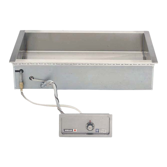
Model HT-300AF
This manual is considered to be part of the appliance and is to be given to the OWNER or
MANAGER of the restaurant, or to the person responsible for TRAINING OPERATORS of
this appliance. Additional manuals are available from your WELLS DEALER.
THIS MANUAL MUST BE READ AND UNDERSTOOD BY ALL PERSONS USING OR
INSTALLING THIS APPLIANCE. Contact your WELLS DEALER if you have any
questions concerning installation, operation or maintenance of this equipment.
Rev. A
2M-308086
265 Hobson Street, Smithville, Tennessee 37166
IMPORTANT: DO NOT DISCARD THIS MANUAL
WELLS MANUFACTURING
telephone: 314-678-6314
fax: 314-781-2714
www.wells-mfg.com
OWNER'S MANUAL
HT200AF, 227AF
HT300AF, 327AF
HT400AF, 427AF
HT500AF, 527AF
WIRING DIAGRAM
021B
BUILT-IN
BAIN MARIE
STYLE
HEATED TANKS
with AUTOFILL
MODELS
Includes
INSTALLATION
USE & CARE
EXPLODED VIEW
PARTS LIST
03/18
Advertisement
Table of Contents

Subscribe to Our Youtube Channel
Related Manuals for Wells HT200AF


Summary of Contents for Wells HT200AF
- Page 1 Additional manuals are available from your WELLS DEALER. THIS MANUAL MUST BE READ AND UNDERSTOOD BY ALL PERSONS USING OR INSTALLING THIS APPLIANCE. Contact your WELLS DEALER if you have any questions concerning installation, operation or maintenance of this equipment.
- Page 2 Wells’ discretion have the parts replaced or codes, including incorrect gas or electrical connection. Wells is not liable repaired by Wells or a Wells-authorized service agency.
-
Page 3: Electrical Specifications
PARTS & SERVICE CUSTOMER SERVICE DATA INTRODUCTION Thank You for purchasing this Wells Bloomfield appliance. Proper installation, professional operation and consistent maintenance of this appliance will ensure that it gives you the very best performance and a long, economical service life. -
Page 4: Features & Operating Controls
FEATURES & OPERATING CONTROLS A. THERMOSTAT INDICATOR LIGHT On THERMOSTATICALLY CONTROLLED heated tanks, power is applied to the heating element according to the control knob position and the actual temperature at the temperature sensing thermobulb. The desired temperature is controlled by rotating the TEMPERATURE TEMPERATURE CONTROL KNOB. -
Page 5: Precautions And General Information
Do not operate this appliance if the control panel is damaged. Call these instructions are not your Authorized Wells Service Agent for service. followed. The technical content of this manual, including any wiring diagrams, schematics, parts breakdown illustrations and/or adjustment procedures, is intended for use by qualified technical personnel. -
Page 6: Installation
INSTALLATION NOTE: DO NOT discard UNPACKING & INSPECTION the carton or other packing Carefully remove the appliance from the carton. Remove all materials until you have protective plastic film, packing materials and accessories from the inspected the appliance for Appliance before connecting electrical power or otherwise performing hidden damage and tested it any installation procedure. - Page 7 INSTALLATION 3. For “top-mounted” installation: a. Verify that provided sealants are applied to the underside of the warmer top flange prior to setting the unit into the cutout. IL2456 b. After installation, verify that the tabs on the Wellsloks are turned out to lock the warmer into the counter.
-
Page 8: Operation
OPERATION CAUTION: A. WET OPERATION HOT SURFACE Make sure the drain valve is fully closed before turning thermostat ON. Add approximately 1” of hot tap water before turning the warmer ON. Exposed surfaces can be hot to the touch and may cause Use of hot water will allow a faster preheat. -
Page 9: Maintenance Instructions
Never use metal implements, wire brushes, abrasive scratch pads or steel wool to clean stainless steel. Warmer pans, insets and other vessels are subject to a harsher environment. Wells Manufacturing uses an very high quality stainless steel (#304DDQ) for our food warmer pans. -
Page 10: Cleaning Instructions
Contact your Authorized Wells Service Agency to inspect warmer if water or grease contamination is suspected. Add proper amount of warm water. Turn control knob ON and... - Page 11 CLEANING INSTRUCTIONS WEEKLY CLEANING INSTRUCTIONS PREPARATIONS: Remove any insets, pans and/or adapter tops. Drain or remove water from well if used for wet CAUTION: operation. CHEMICAL BURN HAZARD FREQUENCY: Weekly, or whenever lime or scale is seen accumulating on the sides of the warmer pans. Deilimng chemicals may be caustic.
-
Page 12: Troubleshooting Suggestions
Too much water Remove water from pan until 1” of water remains in tank There are no user-serviceable components in this appliance. In all instances of damage or malfunction, contact your Authorized Wells Service Agency for repairs. -
Page 13: Exploded View And Parts List
EXPLODED VIEW & PARTS LIST HT-200AF and HT-227AF DRAIN SCREEN DRAIN SCREEN P2-31869 P2-31869 ADAPTER BAR ADAPTER BAR P2-301893 P2-303012 REAR REAR SHROUD SHROUD HT227AF P2-301761 HT200AF P2-301761 SIDE SIDE SHROUD SHROUD P2-302882 P2-303359 ELEMENT CLIP 2C-30397 ELEMENT CLIP 2C-30397 HEATING HEATING ELEMENT ELEMENT... - Page 14 EXPLODED VIEW & PARTS LIST HT-300AF and HT-327AF DRAIN SCREEN DRAIN SCREEN P2-31869 P2-31869 ADAPTER BAR ADAPTER BAR P2-303012 P2-301893 FRONT/REAR FRONT/REAR SHROUD HT327AF SHROUD P2-304105 HT300AF P2-304105 SIDE SHROUD P2-302882 SIDE SHROUD P2-303359 ELEMENT CLIP ELEMENT CLIP 2C-30397 2C-30397 HEATING HEATING ELEMENT...
- Page 15 EXPLODED VIEW & PARTS LIST HT-400AF and HT-427AF DRAIN SCREEN DRAIN SCREEN P2-31869 P2-31869 ADAPTER BAR ADAPTER BAR P2-303012 HT-427AF P2-301893 HT-400AF FRONT/REAR FRONT/REAR SHROUD SHROUD P2-304106 P2-304105 SIDE SHROUD P2-302882 SIDE ELEMENT CLIP SHROUD 2C-30397 P2-303359 HEATING ELEMENT CLIP ELEMENT 2C-30397 500706...
- Page 16 EXPLODED VIEW & PARTS LIST HT-500AF DRAIN SCREEN P2-31869 ADAPTER BAR P2-301893 HT500AF FRONT/REAR SHROUD P2-304105 WATER LEVEL PROBE WS-503713 SIDE SHROUD P2-303359 ELEMENT CLIP 2C-30397 HEATING ELEMENT 2N-46660UL ELEMENT PAN WS-501759 THERMOBULB BOTTOM COVER BRACKET w/ DRAIN P2-301871 D8-303352 BALL VALVE 2V-47847 BOTTOM COVER...
- Page 17 EXPLODED VIEW & PARTS LIST HT-527AF DRAIN SCREEN P2-31869 ADAPTER BAR P2-303012 HT527AF FRONT/REAR SHROUD P2-304107 WATER LEVEL PROBE WS-503713 SIDE SHROUD P2-302882 ELEMENT CLIP 2C-30397 HEATING ELEMENT 2N-300706UL ELEMENT PAN P2-302883 THERMOBULB BRACKET D8-303352 BOTTOM COVER w/ DRAIN P2-302997 BALL VALVE 2V-47847 BOTTOM COVER...
-
Page 18: Wiring Diagram
WIRING DIAGRAM HT-200AF and HT-227AF... - Page 19 WIRING DIAGRAM HT-300AF and HT-327AF...
- Page 20 WIRING DIAGRAM HT-400AF and HT-427AF...
- Page 21 WIRING DIAGRAM HT-500AF and HT-527AF...
- Page 22 NOTES...
-
Page 23: Parts And Service
For factory authorized DRAIN SCREEN P2-31869 service, or to order factory authorized replacement parts, contact your Wells authorized Wellslok Extension Kits for UL Listed units service agency, or call: approved for installation in wood counter tops OPTIONAL 72” WIRING, thermostatically... - Page 24 WELLS MANUFACTURING 265 Hobson Street, Smithville, Tennessee 37166 telephone: 314-678-6314 fax: 314-781-2714 www.wells-mfg.com...
Need help?
Do you have a question about the HT200AF and is the answer not in the manual?
Questions and answers