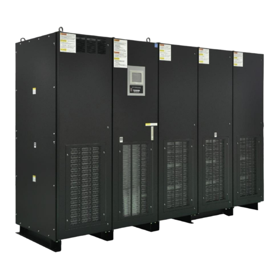
Toshiba G9000 Series Installation Manual
Optional bypass fuse, 480/480 v 1000 kva
Hide thumbs
Also See for G9000 Series:
- Installation and operation manual (104 pages) ,
- Installation manual (24 pages) ,
- Manual (18 pages)

Related Manuals for Toshiba G9000 Series


Summary of Contents for Toshiba G9000 Series
- Page 1 G9000 SERIES OPTIONAL BYPASS FUSE INSTALLATION GUIDE 480/480 V 1000 kVA Doc. No.: 92932-001 Document: 4GBH0090 Rev. B March 2020...
- Page 3 The sales contract contains the entire obligation of TOSHIBA INTERNATIONAL CORPORATION. The warranty contained in the contract between the parties is the sole warranty of TOSHIBA, and any statements contained herein do not create new warranties or modify the existing warranty.
- Page 4 TOSHIBA shall not be liable for technical or editorial omissions or mistakes in this manual. Nor shall it be liable for incidental or consequential damages resulting from the use of information contained in this manual.
-
Page 5: Table Of Contents
Table of Contents List of Figures ..............................iii List of Tables ..............................iii OVERVIEW ............................1 PARTS LIST ............................1 OPTIONAL BYPASS FUSE LOCATION ....................2 INSTALLATION PROCEDURE ......................2 List of Figures Figure.1 Part appearance of 170M6421 ....................1 Figure.2 Front view of G9000 UPS with the door and the access panel open ........ -
Page 6: Overview
OVERVIEW Your TOSHIBA Uninterruptible Power Supply System (UPS) can be equipped with bypass fuses to prevent an overcurrent from keeping flowing through UPS and the peripheral cabinet in case the short-circuited load is fed by bypass supply. Removable conductors in bypass cabinet can be replaced with the optional bypass fuses. This document describes the installation procedures. -
Page 7: Optional Bypass Fuse Location
OPTIONAL BYPASS FUSE LOCATION 52SU 52SV 52SW Figure.2 Front view of G9000 UPS with the door and the access panel open INSTALLATION PROCEDURE Shock Hazard Remove all power from the UPS before opening access panels. Step 1: Turn off the critical load. Step 2: Turn off the UPS. -
Page 8: Figure.3 Example Of The Installation
Figure.3 Example of the installation Step 09: Secure the UPS access panels. Step 10: Use the G9000 Series UPS Installation and Operation Manual to restore power to the UPS in the proper sequence. Step 11: Restore the UPS to normal operation. -
Page 9: Figure.4 Details Of The Fuse Installation
Contactor 52S* Fuse Top view An indicator on fuse can be checked through this hole. 4 - Φ13 Fuse Fuse Bolt Spring washer Flat washer Bus connected to the contactor 52S* Front view Right side view Figure.4 Details of the fuse installation G9000 1000kVA OPTIONAL BYPASS FUSE Installation Guide –... - Page 11 SOCIAL INFRASTRUCTURE SYSTEMS GROUP POWER ELECTRONICS DIVISION 13131 West Little York Rd., Houston, TX 77041 Tel: 713/466-0277 Fax 713/466-8773 US 877/867-8773 Canada 800/872-2192 Mexico 01/800/527-1204 www.toshiba.com/tic/industrial/uninterruptible-power-systems Printed in USA...
Need help?
Do you have a question about the G9000 Series and is the answer not in the manual?
Questions and answers