Table of Contents
Advertisement
Quick Links
Operating and Installation Instructions
EWFS Uniswitch
Keep for future use!
Valid from 01 december 2017
General information
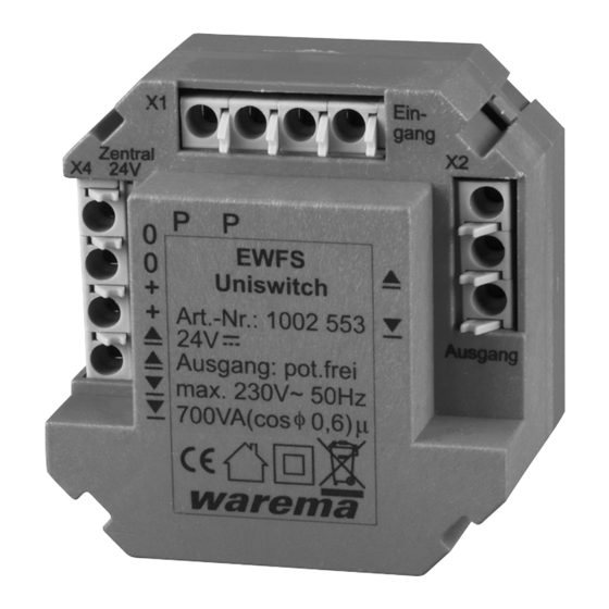
Fig. 1
EWFS Uniswitch
The EWFS Uniswitch radio receiver is an electronic control
unit for the direct control of any motor control unit and can
receive move commands from EWFS-compatible transmit-
ters. The EWFS Uniswitch works in dead man's mode and
has floating switch contacts. In this way, the receiver can
easily be connected in parallel to an existing push button.
The movement behaviour of the connected motor control
unit remains unchanged. The receiver is supplied with 24
V DC either via an existing control line, a floor distribution
control or a power supply unit. Because of its compact
design, the receiver can be installed in a flush-mounted
junction box.
Intended use
The EWFS Uniswitch radio receiver was developed to
control sun shading systems. The approval of the manu-
facturer must be obtained for uses outside of the purpos-
es listed in these instructions.
Safety instructions
W
WARIRG
The electrical installation must be per-
formed by a certified electrician in
accordance with the electrical installation
regulations published by the Wssocia-
tion of German Electrical Engineers (VDE
0100) or the standards and regulations of
the country in which the device is being
installed. The electrician must observe the
Installation instructions included with the
electrical device.
W
WARIRG
If hazard-free operation cannot be
assumed, the device may not be started or
must be deactivated. This assumption is
justified if
the housing or the supply lines show
signs of damage
the device is no longer working.
866088_i•en•2017-12-01
C
WATIIR
Never activate buttons on your transmitter
arbitrarily without visual contact to the sun
shading product. Children may not play with
this product - Remote controls or transmit-
ters must not get into the hands of children!
The range of radio controls is restricted by legal regulations
for radio systems and through structural factors. Adequate
radio reception must be ensured when planning the project.
This applies especially if the radio signal must penetrate
through walls and ceilings. The control unit should not be
installed in the immediate vicinity of metal components
(steel beams, steel-reinforced concrete, fire door).
Therefore, check that the receiver is functioning prop-
n
erly before the final installation.
Strong local transmitter systems (e.g. baby monitors or
neighbouring transmitters) can interfere with the reception.
Function
After the "Up" or "Down" button is pressed on the hand-
held transmitter, the sun shading system moves in the
corresponding direction. The movement behaviour of the
motor control unit is retained. Read the operating instruc-
tions of the connected motor control unit.
Central operation
The local operation is blocked for the duration of a central
command; any current move commands will be deleted.
Symbols used
When the receiver is delivered, it does not "know" any
transmitters initially and first needs to learn to which
transmitters it should respond. We refer to this process as
"learning".
We reserve the right to carry out improvements
1
Advertisement
Table of Contents

Related Manuals for WAREMA EWFS Uniswitch


Summary of Contents for WAREMA EWFS Uniswitch
- Page 1 Strong local transmitter systems (e.g. baby monitors or receive move commands from EWFS-compatible transmit- neighbouring transmitters) can interfere with the reception. ters. The EWFS Uniswitch works in dead man's mode and has floating switch contacts. In this way, the receiver can Function easily be connected in parallel to an existing push button.
- Page 2 The learn button on the transmitter on this procedure can be found in the "EWFS must be pushed within this period or the learn application brochure" at http://www.warema. mode is closed. Push the learn button on your de→Produkte→Steuerungssysteme→...
- Page 3 Auxiliary channels in receiver 1 and 2 are to be deleted. Manifold special functions are additionally possible in Carry out the following operation steps consecutively WAREMA EWFS. Should you wish further information, your with the respective master channel: specialist dealer will be pleased to give you the applica- tion brochure.
- Page 4 Location of use Clean ambient conditions mitter does not ty or depleted operating instruc- Available at www.warema.de light up tions, insert new Conformity declaration batteries The device meets the EMC guidelines for use in residen- Move commands...
- Page 5 MSE Kompakt 1AP / VT MSE Kompakt 1AP / VT MSE Kompakt 1AP / VT Fig. 4 Connection example 866088_i•en•2017-12-01 We reserve the right to carry out improvements...
- Page 6 Fig. 5 Connection example We reserve the right to carry out improvements 866088_i•en•2017-12-01...
Need help?
Do you have a question about the EWFS Uniswitch and is the answer not in the manual?
Questions and answers