Table of Contents
Advertisement
Quick Links
Hoffman
Complete Installation &
Operating Instructions
CAUTION:
Failure to read and understand the accompanying
instructions and diagrams prior to energizing the
890 Sequencer may result in permanent damage to
the sequencer.
General
The Class II 890-DSQ micro controller based universal sequencer
provides a fully programmable platform to sequence multiple
loads using SPDT relay closures. The multiple loads may consist
of condenser fan motors, heating elements, compressors or other
sequencing applications. The 890-DSQ Sequencer's versatility
includes a wide range of input and output options. This universal
sequencer can use 1) up to six (0-5 VDC) temperature sensors or
pressure transducer inputs or 2) a single 0-10 VDC input. The
sequencer also has three 0-10 VDC, EC motor speed control
outputs which can be re-configured as three 10 - 0 VDC motor
speed outputs. There are three, 17.5 volt (80Hz) PWM EC motor
speed control outputs and up to six 24 VAC fixed staged outputs,
with an additional six 24 VAC fixed staged outputs available on
a separate expansion board (total of 12 fixed relay output stages).
The 890-DSQ can be setup as a traditional sequencer or as a true
continuous vernier sequencer, when using continuously variable
EC motors or SCRs as the (VS) variable stage. The sequencer can
be operated locally, using the 5 push buttons and the information
shown on the LCD screen or remotely using a Modbus RTU master
control.
The 890-DSQ Series sequencers require 24 VAC (1 VA) to
power the control.
IMPORTANT:
When using the 890-DSQ Sequencer, select
a transformer to meet the requirements of all the 24 VAC compo-
nents being used.
Introduction
The 890-DSQ Series sequencer is typically used, in an A/C
system, to sequence multiple condenser fan motors, on and off,
to provide low ambient condenser control. The 890 has up to six
temperature or pressure inputs that are used to sequence up to 12
fixed speed condenser fan motors or other loads.
A unique feature is that the 890 also provides three (3) PWM,
or three (3) 0-10 VDC or three (3) 10-0 VDC outputs that are
used to drive continuously variable speed EC fan motors. When
the variable speed fans are present, the sequencer intelligently
modifies the output to the variable speed fans so that, as the addi-
tional fixed speed fans are sequenced on or off, the overall effect is
that the total fan outputs' airflow varies continuously over the
total fan outputs' airflow varies continuously over the
|
Controls
890-DSQ Series Microprocessor
Based Universal Sequencer
entire range. Typically, a mix of PSC and continuously variable
entire range. Typically, a mix of PSC and continuously variable
speed EC powered motors are used within the same condenser
speed EC powered motors are used with
bank. .
bank
The advantage of continuously variable airflow is that it that
the head pressure can be more accurately maintained than by only
switching the condenser fan motors on and off.
The 890-DSQ Sequencer's variable stage operates as follows:
When the next fixed speed fan is turned on, the variable speed fans
drop in rpm to compensate for the additional fixed speed fan. As
the sensor input continues to go up, the variable speed fans in-
crease speed until the next fixed speed fan turns on, at which point
the variable speed fans drop in rpm again. This process also works
in reverse as the input decreases. Hysteresis is also provided so that
no short cycling of the fixed speed fans occur.
Set point Values
The 890-Series sequencers can utilize up to two (2) sets of set
point values, a primary set and a secondary set. Each set can utilize
a maximum of 12 stage turn on and turn off values (24 set points).
The primary set of set point values is the set typically used. The
secondary set of set point values can be used, on demand, when-
ever the sequencer's "2ND" input terminal is connected to the
adjacent "GND" terminal thru an external contact closure.
Description
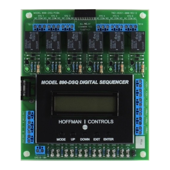
The 890 Control consists of a Kydex covered PCB, on stand
offs, with a 32 character LCD display and five push buttons. The
sequencer can be manually operated by following the LCD's menu
system and selecting the available options, parameters and numer-
ical values, using the 5 push buttons. The LCD display routinely
shows a Home Screen and, when selected, up to 6 mode screens
and a number of additional menu and submenu screens.
The LCD's Home Screen always displays the number of fixed
relay output stages that are turned on, along with the selected
maximum number of stages, and the currently used input's value
(temperature, pressure or 0-10 VDC). When the VS (variable
stage) option is selected, the Home Screen also displays a speed
index (percent) of the continuously variable stage's EC motors
speed or percent of SCRs total output current, along with a
number representing the total of all the relay stages and effective
variable stages that are turned on (see Mode 2.2, page 4.)
Due to the availability of various speed EC motors, the
displayed EC motor speed is shown as a speed index, which is
the percent of full speed (10%, 50%, 76% etc.) that the motor is
operating at. For example: a 1075 rpm variable speed EC motor
showing a speed index of 75 (%) would be running at 806 rpm.
The five push buttons (MODE, UP, DOWN, EXIT and
ENTER) allow the installer to change 1) the number of fixed
stages used, 2) the number of inputs used along with the input
1
in the same condenser
Advertisement
Table of Contents

Related Manuals for Hoffman Controls 890-DSQ Series

Summary of Contents for Hoffman Controls 890-DSQ Series
- Page 1 LCD's menu control. system and selecting the available options, parameters and numer- The 890-DSQ Series sequencers require 24 VAC (1 VA) to ical values, using the 5 push buttons. The LCD display routinely power the control.
- Page 2 Tables 2A & 2B, on pages 16 & 17, to the 890-DSQ Series adjusted, either locally or remotely to suit a particular installation.
-
Page 3: Operating Methods
mmmmmmmmmmmmmmmmmmmmmmmmmmmmm When selected, the LCD's Home Screen also displays the variable Pre-Installation Information/ stage's percent of operation (VS: 75) along with a number repre- Instruction Con't mmmm senting the total of all of the fixed relay stages and effective variable stages that are turned on (2.5). -
Page 4: Operating Modes
Operating Methods Con't Operating Modes The following information is provided to identify and explain the 890-DSQ Sequencer's operational modes, menus, submenus, IMPORTANT: and numerical value options. The sequencer's MODE button is used to sequentially cycle thru the seven (7) available modes After updating any information displayed on the displayed on the sequencer's LCD screen. - Page 5 stage's airflow or a fixed heater element's capacity, due to the elec- tronic components variances in each fixed stage's turn and turn off tolerances. With hysteresis, the EC motor's airflow capacity, or SCR's KW capacity, needs to be much larger than a single fixed stage's on and off values.
- Page 6 3) Emergency On Temp/Pres: 95.0 Operating Modes Con't This screen appears when temperature sensor or pressure transducer inputs are selected. If any of the used temperature 4) Stage On Delay in seconds: 2 sensor or pressure transducer input values reach or exceed the selected Emergency On value (max 115 °F or 1000 PSI), all Use the UP and DOWN buttons to change the delay after of the remaining inactivated relay stages will turn on sequen-...
- Page 7 If VS (variable stage) operation is selected, this screen will appear. Use the UP and DOWN buttons to set the value at The 890-DSQ Series sequencers include a second set of set which the continuously variable EC motors, or SCRs, first points that can be stored and used when an application determined begin to turn on.
- Page 8 stop bits. Then press the ENTER button to save the selected Operating Modes Con't parity and continue. 5) Change Sensor MODE 6: Special Settings: Type: Temperature MODBUS, I&O, RESET Use the UP and DOWN buttons to change the input sensor This mode has 10 menus and is used to set the following options: type.
-
Page 9: Factory Default Settings
Using motors with a 10-0 VDC input control signal pro- Operating Modes Con't vides a level of safety. If the EC motors using a 10-0 VDC input signal loose their control signal they will run at full NOTE: The LCD's Home Screen will show "VS: 0" indicat- speed. - Page 11 The 890-DSQ Series Sequencers may be installed using a range of inputs, staged relay outputs, and continuously variable speed EC motors or SCR outputs. Refer to Figures 5 thru 8, (pages 12 thru 15), for the appropriate wiring diagram(s) for this application.
- Page 12 MODEL 890-DSQ DIGITAL SEQUENCER MODEL 890-DSQ DIGITAL SEQUENCER Hoffman Hoffman Controls Controls MODE MODE EXIT EXIT ENTER ENTER DOWN DOWN Continued on page 18...
-
Page 13: Built-In Self Test
Initial Sequencer Checkout Installation Con't • Verify all wire connections are complete and correct for this appli- cation. • Apply 24 VAC power to the 890-DSQ Sequencer. • Perform all Built-In Self Test instructions (below). Built-In Self Test Figure 6 Liquid Line Temperature Sensor Mounting The Built-In Self Test function can only be operated in manual mode, and only simulates the value of a temperature sensor or... - Page 14 MODEL 890-DSQ DIGITAL SEQUENCER MODEL 890-DSQ DIGITAL SEQUENCER Hoffman Hoffman Controls Controls MODE MODE DOWN DOWN EXIT EXIT ENTER ENTER 0-10V Figure 7 890-DSQ WIRING DIAGRAM 2...
- Page 16 REGISTER REGISTER MODBUS 16 BIT REGISTER FUNCTION NUMBER TYPE VS EC motor or SCR Turn-On Temp (°F), PSI or Volts DC (All values times 10) Read & Write Stage 1, Primary set point's On Temp (°F), PSI or Volts DC. (All values times 10) Read &...
- Page 17 REGISTER REGISTER 16 BIT REGISTER FUNCTION MODBUS NUMBER TYPE Stage 10, Primary set point's On Temp (°F), PSI or Volts DC (All values times 10) Read & Write Stage 11, Primary set point's On Temp (°F), PSI or Volts DC (All values times 10) Read &...
-
Page 18: Modbus Operation
Sequencer Re-calibration Modbus Operation If re-calibration of the 890-DSQ Sequencer's settings or numer- ical values are required, due to the particulars of the application, IMPORTANT: proceed with the following steps: After remotely updating any information the re- 1) Power up loads (motors, heating elements etc.) and 890-DSQ mote operator MUST review ALL of the 890-DSQ Sequencer. -
Page 19: Operating Tips
Operating Tips Speed Adjustment The speed at which the LCD screen's values change is variable. Holding the UP or DOWN button down causes the dislayed value to change slowly at first and then speed up noticably. When FIGURE 9 making large value changes hold the button down until the Input Sensor Values Screen displayed number is close to the desired value. -
Page 20: Troubleshooting Guide
Troubleshooting Guide Condition Cause Solution 1. Check wiring, review instructions. 1. Improper installation, sequencer not wired correctly. 2. Select number of fixed relay stages used. 2. Sequencer's relay stages have not been selected. Relay Stages Will 3. Deselect 0-10 VDC input Not Activate 3.
Need help?
Do you have a question about the 890-DSQ Series and is the answer not in the manual?
Questions and answers