
Related Manuals for Toshiba HCV-7HA


Summary of Contents for Toshiba HCV-7HA
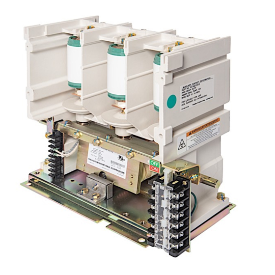
- Page 1 Document: VF00W104 Rev.1 INSTRUCTION MANUAL INSTALLATION - OPERATION - MAINTENANCE HCV-7HA Vacuum Contactor, 7.2kV – 400A – 7.2kA HCV-7HAL Vacuum Contactor, 7.2kV – 400A – 7.2kA Issued: 3/20 Manufactured in the USA...
- Page 3 INSTRUCTION MANUAL For the Installation, Operation and Maintenance of HCV-7HA Vacuum Contactor, 7.2kV – 400A – 7.2kA HCV-7HAL Vacuum Contactor, 7.2kV – 400A – 7.2kA Never attempt to install, operate, maintain or dispose of this equipment until you have first read and understood all of the relevant product warnings and user directions that WARNING are contained in this Instruction Manual.
-
Page 5: Safety
SAFETY Page 1 IMPORTANT MESSAGES Read this manual and follow its instructions. Signal words such as DANGER, WARNING and CAUTION will be followed by important safety information that must be carefully reviewed. Indicates a situation which will result in death, serious injury, and severe property DANGER damage if you do not follow instructions. - Page 6 Be trained in rendering first aid. SAFETY CODES Toshiba HCV-7HA and HCV-7HAL vacuum contactors are designed and built in accordance with NEMA ICS 3, UL347, and CSA 22.2 No. 253 -16. Installations must comply with all applicable state and local codes, adhere to all applicable National Electric Code (NFPA 70) standards and...
- Page 7 SAFETY Page 3 HAZARDOUS VOLTAGE will cause severe injury, death, fire, explosion and property DANGER damage. • Turn off and lock out Primary and Control Circuit Power before servicing. • Keep all panels and covers securely in place. • Never Defeat, Modify, or Bypass any Safety Interlocks •...
-
Page 8: Table Of Contents
Table 3 – Gap/Wipe Standard Values (contactor in new condition) ..............20 Vacuum Check ..............................21 Figure 10 – Toshiba Portable Vacuum Checker ..................... 21 Figure 11 – Application of Test Voltage for Vacuum Check ................22 Electrical Service Life ............................23 Mechanical Service Life ........................... - Page 9 TABLE OF CONTENTS Page 5 Table 4 – Recommended Part Replacement Intervals ................... 23 Figure 13 – Capacitor Switching Life ....................... 23 STORAGE AND DISPOSAL ........................24 Storage ................................24 Inspection During Storage ..........................24 Disposal ................................24 SPECIFICATIONS ........................... 25 Table 5 –...
-
Page 10: Introduction
Page 6 INTRODUCTION It is the intent of this manual to provide a guide for safely installing, operating and maintaining Toshiba vacuum contactors. This manual consists of a section of general safety instructions and is marked throughout with warning symbols. Read this manual thoroughly before installation, operation and maintenance of this equipment. -
Page 11: General Description
INDICATORS PROVIDED COMPONENTS On-Off Indicator – Located on the front, right side of The Toshiba HCV-7HA and HCV-7HAL vacuum the contactor. Indicates if the contactor is OFF contactors described in this manual are suitable for (Green) or ON (Red). When the indicator reads OFF, use on systems of 7.2kV –... -
Page 12: Receiving, Inspection And Handling
CAUTION side or upside down. This may cause damage. File a claim with the carrier for any damaged or missing items and immediately notify the nearest Toshiba representative. Do not install or energize equipment that has been WARNING damaged. Damaged... -
Page 13: Installation
Fasten the contactor using four (4) M8 hex head bolts. The tightening torque should be 120-150 kgf- Toshiba HCV-7HA and HCV-7HAL contactors are cm (9-11 ft-lb). See Table 1 for tightening torque intended for use in usual service conditions as specifications defined in NEMA ICS 1. -
Page 14: Ground Connections
Page 10 INSTALLATION GROUND CONNECTIONS The contactor must be grounded in accordance with the requirements of the National Electrical Code, Article 250 or applicable local standards. Proper grounding connections must be made to WARNING the contactor before incoming power is applied. The ground connection should be made to one of the mounting bolt locations. -
Page 15: Pre-Energization Check
PRE-ENERGIZATION CHECK Page 11 GENERAL ELECTRICAL CHECKS Electrical shock hazard. Do BEFORE ENERGIZING THE CONTACTOR for the not touch energized first time, follow the procedure below to verify that the WARNING equipment is properly installed and functional. components during a test using auxiliary power. -
Page 16: Operation
CONTROL CIRCUITS The HCV-7HA is a Magnetically Held type of contactor. Contactor closing is controlled by the drive unit. The drive unit is a control board that applies a relatively high voltage to the closing coils for a short period of time to close the contactor and then reduces the voltage to the coils for holding the contactor closed. - Page 17 OPERATION Page 13 LEGEND CC ---- Closing Coil 1 & 2 ---- Control Power Input Terminals 3 & 4 ---- Control Switch Input Terminals 5 & 6 ---- Closing Coil Terminals 7 & 8 ---- No Connection Figure 5 - Internal Connection of the Magnetically Held Type LEGEND CC ---- Closing Coil 1 &...
- Page 18 Page 14 OPERATION LEGEND PR ---- Protection Relay PB1 ---- Stop Pushbutton ES ---- Emergency Stop PB2 ---- Start Pushbutton MR ---- Master Relay GL ---- Green Indicator Light RL ---- Red Indicator Light M ---- Vacuum Contactor M/a ---- Aux a Contact M/b ---- Aux b Contact DU ---- Drive Unit CC ---- Close Coils...
- Page 19 OPERATION Page 15 LEGEND PR ---- Protection Relay ES ---- Emergency Stop PB1 ---- Stop Pushbutton TRP ---- Trip Relay PB2 ---- Start Pushbutton MR ---- Master Relay GL ---- Green Indicator Light RL ---- Red Indicator Light M ---- Vacuum Contactor M/a ---- Aux a Contact M/b ---- Aux b Contact DU ---- Drive Unit...
- Page 20 Page 16 OPERATION LEGEND PR ---- Protection Relay ES ---- Emergency Stop PB1 ---- Stop Pushbutton TRP ---- Trip Relay PB2 ---- Start Pushbutton MR ---- Master Relay GL ---- Green Indicator Light RL ---- Red Indicator Light M ---- Vacuum Contactor M/a ---- Aux a Contact M/b ---- Aux b Contact DU ---- Drive Unit...
-
Page 21: Maintenance
MAINTENANCE Page 17 MAINTENANCE PROGRAM MAINTENANCE RECORD In order to ensure continued reliable and safe Keep a permanent record of all maintenance work. operation of the equipment, a program of periodic At a minimum, this record should include information maintenance must be established. Operating and environmental conditions will usually dictate the frequency of inspection required. -
Page 22: Recommended Inspection And Maintenance Types
Page 18 MAINTENANCE RECOMMENDED INSPECTION AND Table 1 - Tightening Torque MAINTENANCE TYPES Screw Nominal Tightening Torque NOTE: Refer to the SAFETY section of this Diameter manual for important information. 1. Acceptance Inspection 15-20 kgf-cm (13-17 in-lb) This inspection confirms that the contactor is 30-40 kgf-cm (26-34 in-lb) complete, correct as specified and undamaged from shipment. - Page 23 Spring Visual inspection. Check for rust, deformation, Wipe with clean dry cloth. discoloration, or damage. Lubricate wipe surface if needed or every 20,000 operations. (Toshiba B9 grease) Smooth Visual inspection Make sure moving parts Apply a small amount of operation or touch.
- Page 24 Dielectric Measure main Measure dielectric 14kV AC or 19.8kV DC If breakdown occurs, Strength circuit strength between for 1 minute contact Toshiba. phases and between circuits and ground. Open/Close ---- Perform open/close ---- If not normal, check Operation operation by electric and repair.
-
Page 25: Vacuum Check
The contactor should be disconnected from the TEST EQUIPMENT: main circuit and be in the OFF position. Toshiba offers a compact vacuum checker (Type Connect all the line side primary terminals CI35-1D, Figure 10) which enables a quick and easy together and to the output of the vacuum checker check on vacuum interrupter internal pressure. - Page 26 Page 22 MAINTENANCE CRITERIA: If a current flow above 5 milliamperes is observed or if breakdown occurs, one or more of the 1 minute interrupters has insufficient vacuum and must be 10kV AC replaced. (14kV DC) Exception: If the current exceeds 5 milliamperes the first time the voltage is brought up, reduce the voltage to zero and increase it again.
-
Page 27: Electrical Service Life
MAINTENANCE Page 23 ELECTRICAL SERVICE LIFE SERVICE LIFE – CAPACITOR SWITCHING The electrical service life of the vacuum Switching of capacitor loads produces severe interrupter is defined by the electrode wear and conditions for contactors, such as high the number of open/close operations frequency inrush current and phase-to-phase (mechanical life). - Page 28 Page 24 SPECIFICATIONS STORAGE If the contactor is to be stored for any length of time prior to installation, the following precautions should be taken. 1. The original packing should be restored, if possible. 2. Do not subject the equipment to moisture or sunrays.
- Page 29 SPECIFICATIONS Page 25 Table 5 – Ratings Items HCV-7HA HCV-7HAL Rated Maximum Voltage Rated Operation Voltage 1501-6900 Rated Current Rated Frequency 50/60 Interrupting Capacity Rated Insulation Level (BIL) Rated Insulation Level (Power-frequency withstand) 18.2 Rated Short-Time Current 6.0 – 1 sec., 2.4 – 30 sec.
- Page 31 Transmission & Distribution Division 13131 West Little York Road | Houston, TX 77041 Tel: 713-466-0277 | US: 800-231-1412 | CAN: 800-872-2192 www.toshiba.com/tic Printed in USA...
Need help?
Do you have a question about the HCV-7HA and is the answer not in the manual?
Questions and answers