Sign In
Upload
Download
Add to my manuals
Delete from my manuals
Share
URL of this page:
HTML Link:
Bookmark this page
Add
Manual will be automatically added to "My Manuals"
Print this page
×
Bookmark added
×
Added to my manuals
Manuals
Brands
SilverStone Manuals
Enclosure
Temjin Series
Manual
SilverStone Temjin Series Manual
Advanced micro-atx tower chassis with breakthrough storage and cooling capacity
Hide thumbs
1
2
3
4
5
6
7
8
9
10
11
12
13
14
15
16
17
18
19
20
21
22
23
24
25
26
27
28
29
30
31
32
33
34
35
36
37
38
39
40
41
42
43
44
45
46
47
48
49
50
51
page
of
51
Go
/
51
Bookmarks
Advertisement
Quick Links
Download this manual
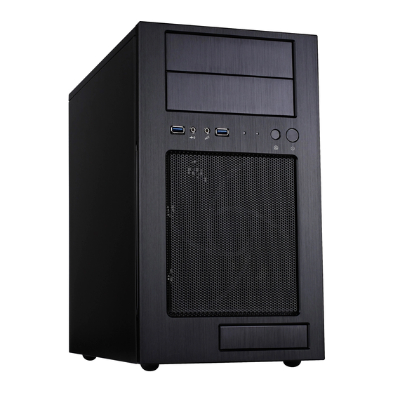
TJ08-E
May, 2011
Advanced Micro-ATX tower chassis with
breakthrough storage and cooling capacity
NO: G11214080
Previous
Page
Next
Page
1
2
3
4
5
Advertisement
Need help?
Do you have a question about the Temjin Series and is the answer not in the manual?
Ask a question
Questions and answers
Related Manuals for SilverStone Temjin Series
Enclosure SilverStone TJ07 Manual
Temjin series computer case (12 pages)
Enclosure SilverStone TJ07 Manual
(11 pages)
Enclosure SilverStone TS07 Manual
External 3.5" hdd enclosure (45 pages)
Enclosure SilverStone TS06 Manual
Treasure series (31 pages)
Enclosure SilverStone ts231u User Manual
2 bay 3.5" hdd raid enclosure with usb 3.0/esata interface (16 pages)
Enclosure SilverStone ts02b User Manual
Treasure series (8 pages)
Enclosure SilverStone TS231U-C User Manual
Dual-bay 3.5" raid enclosure with usb 3.1 type-c (56 pages)
Enclosure SilverStone TS432U User Manual
Four bay 3.5" hdd raid tower with lcd and duplication mode (148 pages)
Enclosure SilverStone TJ08-E Manual
Advanced micro-atx tower chassis with breakthrough storage and cooling capacity (51 pages)
Enclosure SilverStone TJ04-E Manual
(47 pages)
Enclosure SilverStone TS10 Installation Manual
(2 pages)
Enclosure SilverStone Temjin SST-TJ11B-W Manual
Temjin series tj11 (43 pages)
Enclosure SilverStone Precision PSO1-E Manual
Silverstone precision pso1-e pc case (16 pages)
Enclosure SilverStone Lascala LC11 Manual
Silverstone lascala series manual (7 pages)
Enclosure SilverStone SST-SG02-f Manual
Sugo series (17 pages)
Enclosure SilverStone SG04-FH Manual
Sugo series (34 pages)
This manual is also suitable for:
Tj08-e
Sst-tj08b-e
Print
Rename the bookmark
Delete bookmark?
Delete from my manuals?
Login
Sign In
OR
Sign in with Facebook
Sign in with Google
Upload manual
Upload from disk
Upload from URL


Need help?
Do you have a question about the Temjin Series and is the answer not in the manual?
Questions and answers