Table of Contents
Advertisement
Quick Links
Advertisement
Table of Contents

Subscribe to Our Youtube Channel
Related Manuals for Ruska Instrument 7010


Summary of Contents for Ruska Instrument 7010
- Page 1 RUSKA MODEL 7010 DIGITAL PRESSURE CONTROLLER USER’S MANUAL...
- Page 2 DIGITAL PRESSURE CONTROLLER MODEL 7010 USER’S MANUAL RUSKA INSTRUMENT CORPORATION 10311 WESTPARK DRIVE, HOUSTON, TEXAS 77042 (713) 975-0547 FAX: (713) 975-6338 E-MAIL: ruska@ruska.com Release: 7010-1D01 Revision: F Date: 01/02/02...
- Page 3 WARRANTY Ruska Instrument Corporation warrants its products to conform to or exceed the specifications as set forth in its catalogs in use at the time of sale and reserves the right, at its own discretion, without notice and without making similar changes in articles previously manufactured, to make changes in materials, designs, finish, or specifications.
-
Page 4: Copyright Notice
COPYRIGHT NOTICE Copyright © 1997 by Ruska Instrument Corporation. All rights reserved. This document may not be reproduced in part or in whole without the express written consent of Ruska Instrument Corporation. DISCLAIMER No representations or warranties are made with respect to the contents of this user’s manual. -
Page 5: Revision Notice
REVISION NOTICE DATE OF RELEASE DESCRIPTION NUMBER RELEASE 7010-1D01 11/10/93 Original release 9/16/94 Text changes, ECO-19492 7010-1D01 Text & drawing changes, ECO- 4/20/95 7010-1D01 19578 Text & drawing changes, ECO- 6/16/97 7010-1D01 17791 7010-1D01 07/29/99 Text changes per ECO-17805. 7010-1D01... -
Page 6: Revision History
REVISION HISTORY RELEASE 7010-1D01 Revision A (11/10/93) .Original release. RELEASE 7010-1D01 Revision B (9/16/94) Text changes, ECO 19492. RELEASE 7010-1D01 Revision C (4/20/95) Text & drawing changes, ECO 19578. RELEASE 7010-1D01 Revision D (6/16/97) Text & drawing changes, ECO 17791. -
Page 7: Safety Summary
SAFETY SUMMARY The following are general safety precautions that are not related to any specific procedures and do not appear elsewhere in this publication. These are recommended precautions that personnel must understand and apply during equipment operation and maintenance to ensure safety and health and protection of property. -
Page 8: Table Of Contents
2.3.5 FRONT PANEL ................... 2-3 PNEUMATICs MODULE ................. 2-4 2.4.1 MEASURE MODE PNEUMATICS ............2-6 2.4.1.1 Reference Port ............... 2-6 2.4.1.1.1 Special Consideration for 1 psi 7010 ......... 2-6 2.4.1.2 Test Port................2-7 2.4.1.3 Vent Port................2-7 2.4.2 CONTROL MODE PNEUMATICS............2-8 2.4.2.1 Pressure Supply Port .............. - Page 9 SECTION 3.0: INSTALLATION INTRODUCTION................... 3-1 UNPACKING THE DPC .................. 3-1 CAUTIONS ....................3-1 POWERING UP THE DPC................3-1 3.4.1 OBSERVING THE DPC’S FULL SCALE RATING ........3-1 PNEUMATIC CONNECTIONS................ 3-2 3.5.1 PRESSURE SUPPLY PORT..............3-2 3.5.2 SUPPLY VACUUM................3-2 3.5.3 TEST PORT..................3-3 3.5.4 REFERENCE PORT ................
- Page 10 4.5.5 ENABLE ERROR ................4-14 4.5.6 DATE/TIME ..................4-14 MEMORY CARD ..................4-14 4.6.1 CARD SUPPORT ................4-14 4.6.2 SAVING/RESTORING SETUP INFORMATION ........4-14 4.6.3 SAVING/RESTORING CALIBRATION INFORMATION ......4-15 4.6.4 SAVING/RESTORING PROGRAMS............. 4-15 SECTION 5.0: REMOTE OPERATION CAPABILITIES 5-1 5.1.1 IEEE-488....................
- Page 11 LIST OF FIGURES FIGURE 2-1: MODEL 7010 BLOCK DIAGRAM .............. 2-1 FIGURE 2-2A: MODEL 7010 DPC DIFFERENTIAL PNEUMATICS DIAGRAM ....... 2-4 FIGURE 2-2B: MODEL 7010 DPC ABSOLUTE PNEUMATICS DIAGRAM ......2-5 FIGURE 2-2C: MODEL 7010 DPC HIGH PRESSURE PNEUMATICS DIAGRAM....2-5 FIGURE 2-3: PRESSURE CONTROL (MULTIPLE STEPS)............
-
Page 12: Section 1.0: General Information
Houston, Texas. This section of the manual provides general information about the DPC and presents its features and options. GENERAL INFORMATION The Ruska Model 7010 DPC uses force-balanced, fused-quartz Bourdon tube technology to provide the precise measurement of pressure. During normal operation, the DPC performs in either Measure mode or Control mode. -
Page 13: Standard Equipment & Options
Friendly Display: The DPC’s vacuum fluorescent display combines a bright, low-glare readout with a wide viewing angle. During normal operation, the measured pressure is easily visible from a distance of 10 feet (3 meters). Adjustable Pressure Display: The pressure display may be adjusted to show one decimal greater than or less than the default resolution. -
Page 14: Table 1-1: Options List For The Model 7010
Additional Power Cords: Additional power cords are available for most countries. All options are summarized in Table 1-1. To order these items, please contact Ruska Instrument Sales in the U.S. at (713) 975-0547. - Page 15 THIS PAGE LEFT INTENTIONALLY BLANK INTRODUCTION...
-
Page 16: Section 2.0: Theory Of Operation
SECTION 2.0 THEORY OF OPERATION INTRODUCTION The DPC's power supply, electronics, pneumatics, and sensor combine to form a complete, stand- alone, measure and control instrument. This section of the manual describes the DPC's component modules (Figure 2-1) and provides a general discussion of each. FIGURE 2–1 DPC BLOCK DIAGRAM POWER SUPPLY... -
Page 17: Electronics Module
ELECTRONICS MODULE 2.3.1 CONTROL BOARD The Control Board monitors every major component of the Electronics Module. Microprocessor Board, the Option Board, the IEEE-488 Interface, and the optional memory cards all plug into the Control Board. The Sensor Board and Front Panel both communicate with the Control Board via ribbon cables. -
Page 18: Option Board
TABLE 2–1 CONVERSION FACTORS Unless specified otherwise, conversion factors are based on ANSI 268–1982. Symbol Description Conversion Factor inHg inches of mercury (0 °C) = kPa x 0.2952998 inHg inches of mercury (60 °F) = kPa x 0.296134 kiloPascals = kPa x 1.0 bars = kPa x 0.01 pounds per square inch... -
Page 19: Pneumatics Module
Components RG01 and RG02 are low pressure regulators. Component SRV01 is a three-port, DC servo valve, with one supply port, one exhaust port, and one output port. RV01 through RV04 are relief valves. See Figures 2-2A and 2-2C. FIGURE 2–2A MODEL 7010 DPC DIFFERENTIAL PNEUMATICS DIAGRAM THEORY OF OPERATION... - Page 20 FIGURE 2–2B MODEL 7010 DPC ABSOLUTE PNEUMATICS DIAGRAM FIGURE 2–2C MODEL 7010 DPC HIGH PRESSURE PNEUMATICS DIAGRAM THEORY OF OPERATION...
-
Page 21: Measure Mode Pneumatics
Additionally, a temperature sensor (TRANSDUCER05) helps keep the quartz Bourdon tube sensor at 50 2.4.1.1.1 SPECIAL CONSIDERATIONS FOR 1 PSI 7010 The 1-4.99 psi version of the DPC requires special handling to assure the full performance of the instrument. -
Page 22: Test Port
temperature changes, the valve would be closed. In an environment with no pressure fluctuations the valve would be wide open. Thus, the appropriate setting varies, but a good compromise can be found. To observe the variations, connect the reference as discussed and open the test port to the atmosphere. -
Page 23: Control Mode Pneumatics
2.4.2 CONTROL MODE PNEUMATICS 2.4.2.1 PRESSURE SUPPLY PORT The Pressure Supply Port connects the user's regulated gas supply (see Section 3.5.1) to the Pneumatics Module, which is protected by a relief valve (RV03). 2.4.2.2 VACUUM SUPPLY (EXHAUST) PORT For many applications, a vacuum pump is not necessary. The Vacuum Supply Port includes a solenoid valve (SV06) that is open only when the DPC is in Control mode. -
Page 24: Figure 2-3 Pressure Control (Multiple Steps)
∫ − − − A dt d S = Setpoint A = Actual V = Control Output p,i,d = Control Coefficients The gain required by the controller is affected by many factors such as volume, absolute pressure, pressure supply, vacuum supply, and hardware variability. To compensate for these factors, the gain is continually updated by the control software. -
Page 25: Figure 2-4: Pressure Control (10% To 20% Steps)
Figure 2–4 shows an expanded view of a step from 10% to 20% of full scale. FIGURE 2–4 PRESSURE CONTROL (10% to 20% STEP) THEORY OF OPERATION 2-10... -
Page 26: Transducer Module
TRANSDUCER MODULE 2.5.1 QUARTZ BOURDON TUBE SENSOR (TRANSDUCER01 The quartz Bourdon tube sensor (TRANSDUCER01 in Figure 2-2A thru 2-2C) is mounted in a machined aluminum/steel housing. The sensor consists of a helical quartz tube with a mirror fixed to one end, as shown in Figure 2-5. A rigid beam is attached transverse to the axis of the helical tube. -
Page 27: Sensor Board
FIGURE 2–6 PHOTOCELL/LIGHT SPOT 2.5.2 SENSOR BOARD A temperature sensor and the quartz Bourdon tube pressure sensor are monitored by the Sensor Board, which works with the Control Board to interpret pressure and temperature signals from these sensors and maintain the sensor housing at 50 °C. 2.5.3 LINEARIZATION TERM As described in the previous section, the relationship between the pressure being measured and the current required to keep the quartz Bourdon tube in its zero position is the main principle... -
Page 28: Auxiliary Sensors
2.5.4 AUXILIARY SENSORS Auxiliary sensors are the case reference pressure sensor, and the oven temperature sensor. These are reference sensors aligned at the factory and are utilized by the firmware which do not require calibration. 2.5.4.1 CASE REFERENCE VACUUM SENSOR The case reference vacuum sensor is a user installed option. - Page 29 Oven Temperature Slope − − 10 . OvenSetpoint OvenTemp ase Pressure Offset CasePressure FullScale Full scale pressure of the 7010 Vacuum Vacuum level for absolute measurements OvenSetpoint Oven temperature setpoint (50.0 °C) OvenTemp Current oven temperature reading Oven temperature offset factor Oven temperature slope facto.
-
Page 30: Using Opto 22 Modules
the CRC checksum is not correct on power-up, the system displays an error message and uses default values (100 psi Differential, Linear calibration, etc.). The following information is stored in EEPROM and is available to the processor on reboot of the controller. -
Page 31: Table 2-3 Opto 22 Modules
TABLE 2–3 OPTO 22 MODULES Module Number Device/Function and Type 0 (reserved) Vacuum supply (exhaust) pump. The pump is turned on whenever vacuum is required at the vacuum supply port 1 (reserved) Supply pressure pump. The pump is turned on whenever pressure is required at the test port. -
Page 32: Section 3.0: Installation
SECTION 3.0 INSTALLATION INTRODUCTION This section of the manual discusses initial installation for the Model 7010 DPC. Installing the DPC involves connecting the supply and test pressure tubing, powering up the unit, and configuring the system through the front panel UNPACKING THE DPC Carefully unpack all components, checking for obvious signs of damage. -
Page 33: Powering Up The Dpc
1. Never operate the DPC with the cover removed. The power supply has internal voltages near 400 volts. 2. Never apply more than 120% of the DPC's full scale as a pressure supply. Pressure supply must be regulated and meet will criteria as stated in Appendix A of this manual. 3. -
Page 34: Supply Vacuum
The vacuum tubing from the pump tot he reference port should be a recommended 1/4-inch inner diameter or larger with a minimum length. If tubing with smaller than recommended inner diameters or long tubing lengths is used, longer pull down times may result. FIGURE 3-1A MODEL 7010 BACK PANEL INSTALLATION... -
Page 35: Figure 3-1B Model 7010 Absolute Back Panel
FIGURE 3-1B MODEL 7010 ABSOLUTE BACK PANEL FIGURE 3-1C MODEL 7010 HIGH PRESSURE BACK PANEL INSTALLATION... -
Page 36: Vacuum Transducer Installation
CAUTION: For DPCs with ranges from 1 to 4.99 psig, the reference port must be left open to atmosphere. Do not apply a positive pressure or a acuum to the reference port on these units. Refer to Figures 2-2A through 2-2C for plumbing information. - Page 37 THIS PAGE INTENTIONALLY LEFT BLANK INSTALLATION...
-
Page 38: Section 4.0: Local Operation
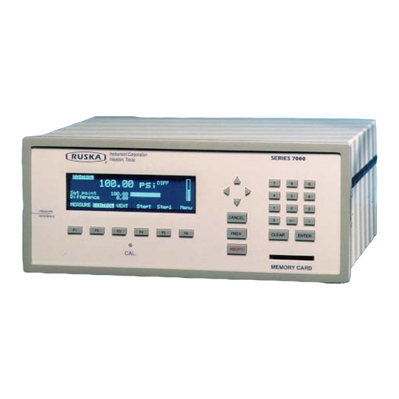
The keys are grouped according to function. FIGURE 4-1 MODEL 7010 FRONT PANEL Numeric Keypad: This includes the number keys, the decimal point [.], and the change sign key [+/-]. The [CLEAR] key will clear the numeric entry field. The [ENTER] key accepts the entered number or confirms a command. -
Page 39: Figure 4-2 Menu Tree
FIGURE 4-2 MENU TREE LOCAL OPERATION... -
Page 40: Tutorial
TUTORIAL To begin the tutorial, first verify that the DPC is powered-up and that the pneumatic connections have been completed. The DPC should display a screen similar to the one shown below. (The bottom line of the display should show the options.) If an error message is displayed, press [F6], then press [PREV.] This is the Main Menu. -
Page 41: Measuring Pressure
Step 5. When the unit desired is highlighted, press the [ENTER] key on the far right side of the front panel, under the numeric keypad. The display will return to the MENU/SETUP screen with the current units. Step 6. Press [PREV.] to return to the MENU screen. Step 7. -
Page 42: Selecting Mode Of Operation
The only mode of operation available for this instrument will be the Absolute mode. 4.2.1.3 Differential Instruments A differential 7010 is capable of operating in Gauge, Absolute and differential modes. Additionally, on some differential units, a negative gauge (or vacuum) option is available which allows the unit to measure and control both positive and negative pressures about the reference pressure. -
Page 43: Differential Model
displayed in the ref. Psi section of the zero screen. The unit will not automatically zero if the case reference pressure is "Out Of Range". See Section 6.4.4 and 6.4.4.2.1. 4.2.1.3.3 Differential Mode The differential instruments are capable of operating in a Differential mode when the case reference is set anywhere from vacuum to 10 psig. -
Page 44: Changing The Number Of Decimals
4.2.4 CHANGING THE NUMBER OF DECIMALS Each unit has a default number of decimal places used for pressure display. This may be adjusted up or down by one decimal place. 1. The decimal digits are set from the Setup User Menu. From the Main Menu (press [PREV.] until the Main Menu appears), press Menu [F6], then Setup [F2], and then User [F2]. -
Page 45: Zeroing
4.2.7 ZEROING Ruska recommends that the DPC be zeroed once a day to maintain optimal performance. Zero drift is a separate specification from precision and stability. The zero drift specification is defined in Appendix A under General Specifications. Refer to section 6.4.4 in this manual for the zeroing procedure. -
Page 46: Programming Sequences
key is held down, the pressure will continue to change until the key is released. The jog increment is fixed, but the step amount may be changed. 1. The step amount is set from the Setup User Menu. From the Main Menu (press [PREV.] until the Main Menu appears), press Menu [F6], then Setup [F2], and then User [F1]. -
Page 47: Entering A New Program
panel to continue the program (refer to paragraph 5 of section 4.4.8; function key [F4] is CONTinue). MaxTime: The max time is the maximum time in seconds, including the dwell time, that the DPC can spend on one step of the program. After the max time elapses, the DPC will automatically proceed to the next setpoint in the program, even if the current setpoint has not been achieved. -
Page 48: Changing The Name Of A Program
4. Press Edit [F4]. Since “new” was highlighted, the DPC will create a new program and give a default name of NAMEnn where nn is a two digit number. The program editing screen will appear, displaying the first step. 5. Press Auto [F3]. 6. -
Page 49: Changing The Configuration Stored With A Program
NOTE: Next [F1] will actually display one step past the end of the program (step 6 of 5). This is to allow adding a step to the end of a program. The step does not actually exist until [ENTER] is pressed. 5. -
Page 50: Sweep Test
4.4.9 SWEEP TEST The sweep function can be utilized to automatically exercise the elastic sensing element of the device under test prior to performing a calibration. For the DPC to perform the sweep test, the user must input the first and last setpoint pressure, the pressure control tolerance, the dwell time at setpoint, and the number of cycles to perform. -
Page 51: Bar Graph Maximum
(hhmmss). All digits must be entered. Press [ENTER] to accept. 4.5.6 FAN OPERATION The 7010 was designed to operate without a fan. However, in some applications where multiple systems are housed in consoles without adequate ventilation, the system may generate Oven Control Failure Error codes. -
Page 52: Memory Card
Press the right arrow key until the number "9" is highlighted. This is the fan solenoid driver. Press Open [F5] to turn the fan on, the Close [F6] to turn the fan off. MEMORY CARD The DPC supports the use of a PCMCIA memory card to store setup, calibration, and program information. - Page 53 3. To erase a program from the card, use the arrow keys to highlight the program to be deleted and press Delete [F2]. LOCAL OPERATION 4-16...
-
Page 54: Capabilities
SECTION 5.0 REMOTE OPERATION The DPC can be operated remotely by a computer. Three interfaces are supported: IEEE-488, RS-232, RS-485. All three interfaces support SCPI (Standard Commands for Programmable Instruments). The IEEE-488 interface additionally supports emulation of a Ruska Single Channel Interface Panel (Models 6005-701 and 6005-761). -
Page 55: Remote/Local Operation
The RS-232 connection is a DB-9P connector found on the back panel of the DPC. It is located on the processor board directly above the DB-25S connector. The following pins are used; all other pins are reserved. Pin # Direction Signal Receive Data Transmit Data... -
Page 56: Device Messages
DEVICE MESSAGES 5.4.1 SCPI COMMAND FORMAT SCPI mnemonics have two forms: long and short. The short form is all in capital letters. The long form is the entire mnemonic. Commands may use either the short form or the entire long form. -
Page 57: Scpi Command Summary
5.4.4. SCPI COMMAND SUMMARY The current value associated with a SCPI command may be read by appending a question mark to the command. For example CALC:LIM:UPP? will return the current upper pressure limit. MEASure [:PRESsure]? Returns Current Pressure Reading :TEMPerature2? Returns Oven Temperature :PRESsure2? Return Case Pressure... - Page 58 :VALue2 <number> Sets Second Calibration Point :TEMPerature2 :DATA <number>, <number> Sets C0, C1 for Oven Temperature :DATA? Reads C0, C1 :VALue <number> Calibrates to Value :MODE? Calibration Edit Enabled? :MODE ON¦OFF¦1¦0 Enable Calibration Edit (Cal. Button Required) DISP :ENABle ON¦OFF¦1¦0 Turns Front Panel Display On/Off :TEXT <string>...
- Page 59 [:AMPLitude] <number> Sets Pressure Setpoint [:AMPLitude]? Read Pressure Setpoint :MODE FIXed|LIST Set Source Parameter Set :TOLerance <number> Specifies Output Tolerance :SLEW <number> Set Slew Rate :LIST :PRESsure <number> [,<number>] Set List of Pressure Values :POINts? Returns Number of Points Defined :DWELl <number>...
-
Page 60: Example Scpi Commands
5.4.5. EXAMPLE SCPI COMMANDS To request the current pressure reading all of the following commands are equivalent: :MEASURE:PRESSURE? :measure:pressure? :MeAsUrE:pReSsUrE? :meas:pres? :measure? :meas? MEAS? To set the control pressure setpoint to 50 all of the following commands are equivalent: SOURCE:PRESSURE:LEVEL:IMMEDIATE:AMPLITUDE 50 SOUR:PRES:LEV:IMM:AMPL 50.0 PRESSURE +50 PRES 50... -
Page 61: 6005 Interface Panel Emulation
Bit 4 Measuring. The instrument is actively measuring. Bit 5 Reserved. 0. Bit 7 Reserved. 0. Bit 8 Self-test in progress. Bit 9 Volume/leak tst in progress. Bit 10 Reserved. 0. Bit 11 Reserved. 0. Bit 12 Reserved. 0. Bit 13 Reserved. 0. Bit 14 Program running. - Page 62 The serial port also supports XON/XOFF. When the XOFF (hexadecimal 13) command is received, the DPC will stop transmitting. Transmission is restarted when the XON (hexadecimal 11) command is received. When only one unit is attached, the Control-C (hexadecimal 03) command will clear the transmit and receive buffers and disable addressing.
- Page 63 THIS PAGE INTENTIONALLY LEFT BLANK REMOTE OPERATION 5-10...
-
Page 64: Section 6.0: Maintenance
NOTE: To run the pneumatic test, supply pressure and a closed test port volume must be connected to the DPC. High pressure versions of the 7010 without the optional test isolation solenoid must have a closed volume of 5 to 15 cubic inches attached to the test port for proper peration of the pneumatic self test. - Page 65 TABLE 6-1 ELECTRONICS SELF TEST TEST DESCRIPTION ACTION ON FAILURE RIC PART # Coprocessor Tests the 80-287 math coprocessor chip Replace chip. 13-932 Replace processor board. 7000-286-16 Clock Tests the real time clock Replace processor board. 7000-286-16 Timer Tests the 10 ms interval timer Replace.
-
Page 66: Removing The Dpc's Cover
6.3.2 REMOVING THE DPC'S COVER The DPC should be kept clean and completely assembled at all times. Operating the DPC without its cover affects the DPC's thermal gradients and therefore reduces precision. If it becomes necessary to remove the DPC's cover, follow the instructions below. CAUTION: The DPC should only be opened by qualified electrical/mechanical service technicians. -
Page 67: Calibration
DPC at any time by "editing the coefficients" (Section 6.4.3). 6.4.1 CALIBRATION INSTRUCTIONS To calibrate the DPC, the user connects a calibration standard such as the Ruska Instrument Model 2465 Gas Piston Gauge to the DPC's test port, then follows the three-step calibration procedure on the DPC's display. -
Page 68: Storing The Coefficients
1.2 Wait until the zero procedure finishes. This may take several minutes. When the DPC completes step 1, the calibration screen will appear. On High Pressure Models, pressure must be removed from the test port. If zeroing in Absolute mode, then the Test Port must be isolated. Step 2 2.1 To begin step 2, use the calibration standard to apply the 50% full scale +/- 5% of full scale pressure requested by the DPC. -
Page 69: Vacuum (Negative Gauge) Calibrations
Step 4 Calibration is complete. To exist the calibration procedure without storing the calibration coefficients in memory, press [CANCEL]. To store the calibration coefficients in memory, select OK [F6]. Step 5 Press [PREV.] to return to the Main Menu. Once the calibration procedure is complete, the user should verify several pressure readings against the pressure standard. -
Page 70: Editing The Calibration Coefficients
test port, close the exhaust valve, and use the pressure controller handwheel to adjust float position. 6.4.3 EDITING THE CALIBRATION COEFFICIENTS If the DPC's memory is erased but the calibration coefficients are known, the user can restore the coefficients to the DPC by following the directions below. CAUTION: Never randomly adjust the calibration coefficients. -
Page 71: Gauge Only Instruments
C Oven: Oven temperature Ref. psi: Case reference pressure (excluded in Absolute mode DPCs). Delay Time: Total time delayed while in zero display. If any of the above are unstable, then the system will delay until stability is achieved. Pressing OK [F6] will bypass this wait period. -
Page 72: Absolute Instruments
For DPCs with ranges from 501 to 2500 psi, a test port isolation valve is not standard. For systems without this valve, it is important to vent the DPC and erify that there is not a pressure source supplying gas into the DPC test port before proceeding with the procedure outlined in Section 6.4.4.1. -
Page 73: Figure 6-5 Photocell Location
8. Perform a normal instrument zeroing procedure. After the unit has become thermally stabilized. Refer to Section 6.4.4. FIGURE 6-5 PHOTOCELL LOCATION MAINTENANCE 6-10... -
Page 74: Section 7.0: Preparation For Storage & Shipment
The DPC must be prepared for shipment in the following manner: 1. Ruska Instrument has an RMA procedure in place. Please contact the Customer Service Center to obtain an RMA number prior to returning any equipment to Ruska. Have the following information available when contacting Ruska: a. -
Page 75: Figure 7-1 Packing The Dpc
The part number, serial number, return address, and purchase order number. 6. Seal the carton using gummed tape. 7. Address the carton to: RUSKA INSTRUMENT CORPORTION 10311 WESTPARK DRIVE HOUSTON, TEXAS 77042 8. Label the carton with the following labels: THIS SIDE UP, HANDLE WITH CARE, DO NOT DROP, and FRAGILE. -
Page 76: Shipping Instructions
SHIPPING INSTRUCTIONS Ruska recommends using air freight for transportation. Surface transportation subjects the shipment to more frequent handling and much more intense shock. In most cases, if surface transportation is the mode of transport employed, handling damage is likely. Again, it is essential that the procedures mentioned in Sections 7.1 through 7.3 be strictly adhered to in order to prevent any shipping and handling damage to the instrument. - Page 77 THIS PAGE INTENTIONALLY LEFT BLANK STORAGE & SHIPMENT...
-
Page 78: Appendix Asummary Of Specifications
APPENDIX A SUMMARY OF SPECIFICATIONS ACCURACY Specifications of pressure transducer instrumentation can be divided into three categories: Input Specifications, General Specifications, and Performance Specifications. Each of these categories in turn consists of parameters that are usually specified by minimum and/or maximum numeric limits. -
Page 79: Specifications
SPECIFICATIONS GENERAL SPECIFICATIONS Pressure Range: 1-2500 psi, 0.07-172 bar Display: Graphical vacuum florescent Electrical Power: 90-260 VAC, 50-400 Hz, 150 W >500 psi 102-120VAC, 60Hz or 102-110VAC, 50 Hz 204-240VAC, 60Hz or 204-220VAC, 50 Hz Operating Temperature: 18-36 Storage Temperature: -20-70 Humidity: 5-95% relative humidity, noncondensing... -
Page 80: Table A-1 Performance Specifications
TABLE A-1 PERFORMANCE SPECIFICATIONS Pressure Range 1-4.9 psi 5-100 psi 101-500 psi 501-2500 psi 15-120 psi (0.07-0.33 bar) (0.34-6.9 bar) (7-34.4 bar) (34.5-172 bar) (1-8.3 bar) Mode Gauge G, A, V G, A, V G, A Absolute 0.004% FS 0.003% FS 0.003% FS 0.003% FS 0.003% FS... -
Page 81: Table A-2 Relief Valve Settings
TABLE A-2 RELIEF VALVE SETTINGS MODEL SUPPLY SUPPLY REFERENCE TEST PORT NUMBER PRESSURE VACUUM PORT 7010-701 5 psig F.S. +15 psig 10 psig 5 psig 7010-702 5 psig F.S. +15 psig 10 psig 10 psig 7010-703 6 psig F.S. +15 psig... -
Page 82: Appendix B: Summary Of Error Messages
APPENDIX B SUMMARY OF ERROR MESSAGES Negative error numbers are from the Standard Commands for Programmable Instruments (Version 1991.0). Value Description and Corrective Action No Error. -103 Invalid Separator. Check punctuation in the SCPI command. -104 Data Type. The type of parameter data is incorrect. -109 Missing Parameter. - Page 83 Value Description and Corrective Action Oven Temp Overrange. Either the transistor that drives the heater for the quartz Bourdon tube sensor (Section 2.0) or the oven temperature sensor itself is malfunctioning. To observe the oven temperature, select OK then select MENU/DISP. Check the transistor and sensor for malfunction, requesting service (Section 7.0) if necessary.
Need help?
Do you have a question about the 7010 and is the answer not in the manual?
Questions and answers