Sign In
Upload
Manuals
Brands
Ruska Instrument Manuals
Controller
7010
Ruska Instrument 7010 Manuals
Manuals and User Guides for Ruska Instrument 7010. We have
1
Ruska Instrument 7010 manual available for free PDF download: User Manual
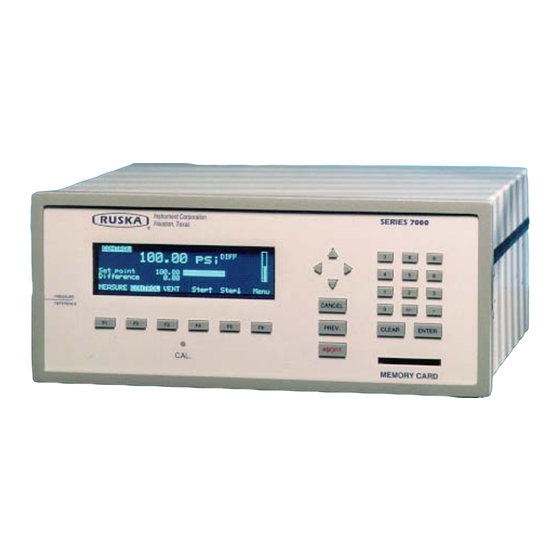
Ruska Instrument 7010 User Manual (83 pages)
DIGITAL PRESSURE CONTROLLER
Brand:
Ruska Instrument
| Category:
Controller
| Size: 1 MB
Table of Contents
Copyright Notice
4
Revision Notice
5
Revision History
6
Safety Summary
7
Table of Contents
8
Section 1.0: General Information
12
Introduction
12
General Information
12
Features
12
Standard Equipment & Options
13
Table 1-1: Options List for the Model 7010
14
Section 2.0: Theory of Operation
16
Introduction
16
Power Supply
16
Electronics Module
17
Control Board
17
Microprocessor Board
17
Option Board
18
Ieee-488 Interface
18
Front Panel
18
Table 2-1 Conversion Factors
18
Pneumatics MODULE
19
Figure 2-2A Model 7010 Dpc Differential Pneumatics Diagram
19
Measure Mode Pneumatics
21
Reference Port
21
Special Consideration for 1 Psi 7010
21
Test Port
22
Vent Port
22
Control Mode Pneumatics
23
Pressure Supply Port
23
Vacuum Supply (Exhaust) Port
23
Pressure Control
23
Control Strategy
23
Figure 2-3 Pressure Control (Multiple Steps)
24
Figure 2-4: Pressure Control (10% to 20% Steps)
25
Transducer Module
26
Quartz Bourdon Tube Sensor (Transducer01)
26
Figure 2-5 Shaft/Magnet Section
26
Sensor Board
27
Linearization Term
27
Figure 2-6 Photocell/Light Spot
27
Auxiliary Sensors
28
Case Reference Vacuum Sensor
28
Software
28
Preventing Operator Errors
28
Pneumatic Errors
28
Shutoffs
28
Oven Control
28
Pressure Reading and Correction
28
Using Opto 22 Modules
30
Table 2-3 Opto 22 Modules
31
Section 3.0: Installation
32
Introduction
32
Unpacking the Dpc
32
Cautions
32
Table 3-1 General Specifications: General Parameters
32
Powering up the Dpc
33
Observing the Dpc's Full Scale Rating
33
Pneumatic Connections
33
Pressure Supply Port
33
Supply Vacuum
34
Test Port
34
Reference Port
34
Figure 3-1A Model 7010 Back Panel
34
Figure 3-1B Model 7010 Absolute Back Panel
35
Figure 3-1C Model 7010 High Pressure Back Panel
35
Vacuum Transducer Installation
36
Section 4.0: Local Operation
38
Figure 4-1 Model 7010 Front Panel
38
Figure 4-2 Menu Tree
39
Tutorial
40
Measuring Pressure
41
Selecting Mode of Operation
42
Gauge Only Instruments
42
Absolute Only Instruments
42
Differential Instruments
42
Absolute Mode
42
Gauge Mode
42
Differential Model
43
Selecting Pressure Units
43
Defining a New Pressure Unit
43
Changing the Number of Decimals
44
Setting the Alarm Limits
44
Using Head Pressure Correction
44
Zeroing
45
Controlling Pressure
45
Setting the Pressure Setpoint
45
Entering/Exiting Control Mode
45
Setting Slew Rate
45
Stepping and Logging
45
Programming Sequences
46
Storing a Sequence in Memory
46
Preparing to Program
46
Entering a New Program
47
Automatically Generating a Program
47
Changing the Name of a Program
48
Changing an Existing Program
48
Changing the Configuration Stored with a Program
49
Running a Program
49
Sweep Test
50
Configuration
50
Calibration Password
50
Test Access Password
50
Bar Graph Maximum
51
Key Click
51
Date/Time
51
Memory Card
52
Card Support
52
Saving/Restoring Setup Information
52
Saving/Restoring Calibration Information
52
Saving/Restoring Programs
52
Capabilities
54
Ieee-488
54
Rs-232
54
Remote/Local Operation
55
Configuration
55
Device Messages
56
Scpi Command Format
56
Scpi Response Format
56
Ansi/Ieee 488.2-1987 Command Summary
56
Scpi Command Summary
57
Example Scpi Commands
60
Scpi Status Registers
60
6005 Interface Panel Emulation
61
Serial Operation
61
Section 6.0: Maintenance
64
Introduction
64
Observing the Software Version Number
64
Preventive Maintenance
64
Initiating the Dpc's Self Test
64
Removing the Dpc's Cover
66
Moisture Filter
66
Particle Filters
66
Vacuum Pumps
66
Processor Battery
66
Calibration
67
Calibration Instructions
67
Preparation
67
Storing the Coefficients
68
Vacuum (Negative Gauge) Calibrations
69
Figure 6-4 Vacuum Calibration
69
Editing the Calibration Coefficients
70
Zeroing
70
Gauge Only Instruments
71
Differential Instruments
71
Gauge Mode
71
Absolute Mode
71
Absolute Instruments
72
Sensor Photocell Zeroing
72
Figure 6-5 Photocell Location
73
Section 7.0: Preparation for Storage & Shipment
74
Disconnecting the Dpc
74
Packing Instructions
74
Figure 7-1 Packing the Dpc
75
Shipping Instructions
76
Appendix Asummary of Specifications
78
Accuracy
78
Specifications
79
Table A-1 Performance Specifications
80
Table A-2 Relief Valve Settings
81
Appendix B: Summary of Error Messages
82
Advertisement
Advertisement
Related Products
Ruska Instrument 7252
Ruska Instrument 7252i
Ruska Instrument 7215
Ruska Instrument 7215i
Ruska Instrument 7215xi
Ruska Instrument Categories
Controller
More Ruska Instrument Manuals
Login
Sign In
OR
Sign in with Facebook
Sign in with Google
Upload manual
Upload from disk
Upload from URL