Advertisement
Quick Links
Control Panel
Operation Manual
Document Ref: SL-014 v1.6
2-Wire
Addressable
O p e r a t i o n , M a i n t e n a n c e a n d S a f e t y I n s t r u c t i o n M a n u a l
SL-014 v1.6 Page1
TOC 635 PLUS
TOC 635 MICRO
A d d r e s s a b l e G a s D e t e c t o r C o n t r o l P a n e l
FS646773
&
V 1 . 6
internationalgasdetectors.com
+44 (0)161 483 1415
@
sales@internationalgasdetectors.com
EMS696504
/international-gas-detectors-ltd
Document Ref: SL-014 v1.6
Triton House
Crosby Street
Stockport
SK2 6SH
Advertisement

Related Manuals for IGD TOC 635 PLUS


Summary of Contents for IGD TOC 635 PLUS
- Page 1 Document Ref: SL-014 v1.6 2-Wire Addressable TOC 635 PLUS & TOC 635 MICRO A d d r e s s a b l e G a s D e t e c t o r C o n t r o l P a n e l O p e r a t i o n , M a i n t e n a n c e a n d S a f e t y I n s t r u c t i o n M a n u a l V 1 .
-
Page 2: Table Of Contents
Document Ref: SL-014 v1.6 Table of Contents Specification Overall Dimensions Interface Wiring Highway Hub Controller Overview Relay Card Overview Relay Card Setup Special Status States Operating System Overview User Actions Menu overview Putting Into Service New Setup Sequence The Sensor ZERO Function Checking Reaction Time The Sensor CALIBRATE Function Help Section... - Page 3 The relationship between the output signal and the gas concentration is linear, the control panel interprets the signal and the gas level is displayed on the RGB backlit display. IGD hold evidence of this linear performance which is available upon request.
- Page 4 Display 2 Lines x 8 Digit LCD Display Multi-Colour Backlight (Red-Alarm, Yellow-Fault, Blue-Normal) User IGD Jog Wheel Option Select, Alarm Reset, RGB Outputs 3 off SPCO Relays 4A Non-Inductive User Configurable 1 off Fault Relay SPCO Relays 4A Non-Inductive 1 off Solid State Beacon Sounder Output...
- Page 5 3. Use equipment and gases traceable to a national standard. Any calibration will only be as good as the equipment and materials used. 4. IGD supply fixed flow regulators for use with IGD calibration gas bottles which supplies gas at 0.5l/min...
- Page 6 IEC 60079-29-1) see examples 110-230V AC 50/60Hz 57W Supported Installation Cables 2 Core 1.0 or 1.5mmSQ See IGD Cable System Calculator Typically SWA, MICC, FP200, SY, CY, System cables must be screened, refer to installers guide SL-014 v1.6 Page6...
- Page 7 Copies of the installation guide are available in the downloads section of our website. Always check you are using the latest versions of the supplied manuals by checking on the IGD website. Failure to follow correct installation may result in poor performance and/or damage to system components.
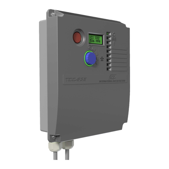
- Page 8 T635 PLUS Control Panel & 2 Wire Hub Controller PCB Features & I/O Addresses Document Ref: SL-014 v1.6 Fitted to Controller PN TOC-635-PLUS Display TOC-650/635 (2x8 LCD) Note that addressable inputs and outputs on Battery Backup the hub card and display are on Highway 0 Address Fault Relay Address...
- Page 9 T635 PLUS Control Panel & 2 Wire Hub Controller PCB Features & I/O Addresses Document Ref: SL-014 v1.6 Note that addressable inputs and outputs on the hub card and display are on Highway 0 E-Stop Button Address 4 Power LED General Alarm LED System Fault LED Battery Backup LED, RED on Battery...
- Page 10 Once logged in you have options to download event logs, download and edit the controllers setup, generate the panel production test certificate and more. Please refer to IGD’s on-line ENGINEER Select ENGINEER Enter password 50 and Login Note: Iphones can be slow to connect depending on setup.
- Page 11 Note that whilst editing a controller setup you MUST stay within WiFi range. If you want to edit a downloaded setup offline, IGD provide a website that allows you to open, view and edit a previously downloaded and stored setup.
- Page 12 Tocsin Series Addressable Relay Card Setting Relay Addresses (compatible with Tocsin 635, 650 & 750) Document Ref: SL-014 v1.6 Each Addressable relay card must have its own unique base address. This can be set on the card and is indicated below. The relays are then addresses/numbered from that base address.
- Page 13 Document Ref: SL-014 v1.6 Tocsin Series Addressable I/O Card (compatible with Tocsin 635, 650 & 750) In all Cases: Relay contact ratings. 5A @ 250V AC Non-Inductive 5A @ 30V DC Non-Inductive Power out for 0V DC Spike suppression must be fitted use in conjunction 24V DC...
- Page 14 Relay cards also have analogue and digital inputs that can be used to read data onto the system from external devices. Setup of the inputs, type, range, addressing etc is controlled via IGD’s Android Apps. Wiring options are indicated below. Note the differences between Version 1 and 2 PCB assemblies.
-
Page 15: Special Status States
Special Status States Document Ref: SL-014 v1.6 State Indication State Warm up On Screen Count Down ‘Blue’ Modbus State Available* Fault Relay Normal Alarm Relays Normal Fault Communication Comms Error Displayed ‘Yellow’ Modbus State Available* Fault Relay Active Alarm Relays Normal Fault Over Range Channel/Display Indication Yellow Modbus State Available*... -
Page 16: User Actions
User Actions..Day to Day Operation Document Ref: SL-014 v1.6 Once fully installed the TOC-635 controller will continuously monitor connected gas detectors and sensors and compare current values with any set alarm thresholds. The display will cycle to display each channel in turn. Display and jog wheel Use Channel Gas or Reading... - Page 17 Controller Interface Overview Document Ref: SL-014 v1.6 Colour Backlit LCD Display Flashes Red on alarm Flashes Yellow on Fault Detection Blue during menu operation Typical display during warm up WARMUP 600s Power LED (Green) Alarm Indicator LED (Red) Emergency Flashes on Alarm Alarm - Stop Fault Detected Indicator LED (Yellow)
- Page 18 Setup option if calibrating or actions. channels, Modbus addressing etc. accessing the connected devices using a laptop running IGD Configurator software. Inhibiting the panel means it stops communicating to connected devices this prevents alarms or data clashes during PC access.
-
Page 19: Menu Overview
Document Ref: SL-014 v1.6 TOC-635-PLUS Menu Overview Engineer Menu Options User Menu Options Provides access for Provides access for control panel set up and diagnostic functions maintenance functions Use this option to FIND Use this option to ZERO connected Input devices. connected devices Use this option to Use this option to CALIBRATE... - Page 20 Document Ref: SL-014 v1.6 TOC-635-MICRO Menu Overview Engineer Menu Options User Menu Options Provides access for Provides access for control panel set up and diagnostic functions maintenance functions Use this option to FIND Use this option to ZERO connected Input devices. connected devices Use this option to Use this option to CALIBRATE...
- Page 21 TOC-635 Menu Overview Document Ref: SL-014 v1.6 Production Menu Options Provides access for control panel set up and diagnostic functions Use this option to Reset the Hubcard (System Re-boot) Reset Hubcard to defaults Display Self Test Not Used Not Used Use to Move to the User (100) Menu Use to Move to the...
-
Page 22: Putting Into Service
Perform a Relay FIND 1 of 12 With Sensors and Relays Installed download the panel setup to IGD’s Panel Seup App to configure the system. It will be necessary to upload this once completed and re-start the controller for it to take effect. - Page 23 Document Ref: SL-014 v1.6 Warm Up Period With power applied the system should undertake its power up sequence and then commence a warm up period. The warm up period is there to allow WARMUP connected detectors to stabilise before operation. Note that certain detector 600s types, Oxygen sensors in particular take longer to stabilise.
- Page 24 Check cable and glands are of suitable type for both the area of application and load carrying capacity. Ensure terminations via glands provide a positive seal.IGD Gland packs PN TOC-GLAND achieve minimum requirements when correctly installed Leave all interfaces unplugged and check installation cabling terminations following IGD 2-Wire Installers Guide, check website for latest revisions.
- Page 25 Sequence for a Complete New Setup Document Ref: SL-014 v1.6 If you need to perform a complete new set up Then presuming the system is correctly installed and cabled the process would be as follows: 1. Use the FIND command to discover connected devices and install them to the controller 2.
- Page 26 Set controller cause and effect Set alarm levels Set detector and relay tag lines Use the IGD online training academy to access online training content for the correct use of these apps. For details to access these courses contact IGD. SL-014 v1.6 Page26...
- Page 27 Alarm Actions and Alarm Levels Document Ref: SL-014 v1.6 Once the alarm level has been set you then need to set the Alarm TYPE and decide which relay activates once the set alarm level is breached. The following sequence continues from the previous page and describes the set up sequences Scroll to change selection LEVEL...
- Page 28 The levels set are published in IGD document “OIGD193". Always refer to the latest version of this published in the downloads section of the IGD website. The enclosed sample document is for indication only, levels will change as new guidance is issued by governing authorities.
- Page 29 Gas Detector ZERO Function Document Ref: SL-014 v1.6 All gas detectors will require periodic ZERO and CALIBRATION. The calibration interval depends on a number of environmental factors such as: temperature variance, exposure to wind chill, rain, humidity changes and vibration to list a few.
- Page 30 Procedure for check reaction time to gas Ensure detector is at zero +/- 1% LEL Use standard IGD professional gas introduction kit with 2M hose. Connect calibration gas but do not turn on Using a stop watch turn on the calibration gas and time to 50% and 90% LEL...
- Page 31 Gas Detector CAL Function Document Ref: SL-014 v1.6 Gas detectors must be calibrated with known calibration gases traceable to National Standards. As previously discussed detectors require regular calibration. Calibration gases should have values chosen that either: a) Are at the alarm set point to get maximum accuracy at this point b) Are between 50 to 90% of the range of the detector.
- Page 32 Interfacing to the Remote Modbus Port (635 PLUS Only) Document Ref: SL-014 v1.6 The TOC 635 controller has an in-built memory map allowing access to alarm status, panel status, readings etc using Modbus RTU protocol. Wiring between units is as follows: RS485 Modbus Comms Port Master DCS/BMS...
- Page 33 MODBUS INTERNAL MEMORY MAP ADDRESSES Document Ref: SL-014 v1.6 FUNCTIONS: Command Function Register Sensor Returned Word Read Sensor Conc 30,001 to 30,999 1 to 999 Min = 0 (-10% LEL) Max = 1200 (110% LEL) Resolution = 0.1% Read Sensor Volts 31,001 to 31,999 1 to 999 Min = 0...
-
Page 34: Troubleshooting
Document Ref: SL-014 v1.6 Troubleshooting State Indication State Warm up On Screen Count Down ‘Blue’ Modbus State Available* Fault Relay Normal Alarm Relays Normal Fault Communication Comms Error Displayed ‘Yellow’ Check Wiring to Detector Nodes Check Terminator is fitted Fault Over Range Channel/Display Indication Yellow Follow Site Safe Operating Procedure, ventilate area.
Need help?
Do you have a question about the TOC 635 PLUS and is the answer not in the manual?
Questions and answers