Table of Contents
Advertisement
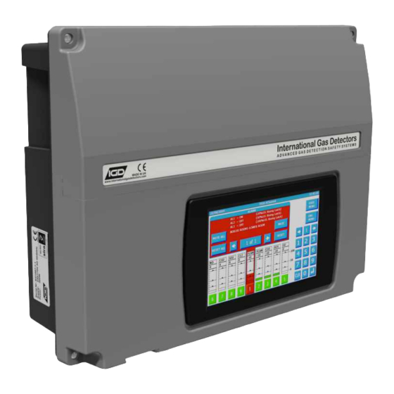
TOCSIN 750 SERIES
Triton House
Crosby Street
Stockport
SK2 6SH
England
ACCESS
KEY
TOC-750R-24
International Gas Detectors
Advanced Addressable Gas Detection System
H M I B a s e d D e t e c t o r C o n t r o l P a n e l
O p e r a t i o n a n d M a i n t e n a n c e
T el: +44 (0)161 483 1415
Fax: +44 (0) 161 484 2345
Email: sales@internationalgasdetectors.co.uk
Website: www.internationalgasdetectors.co.uk
V 3 . 6 1
1
EMS696504
FS646773
REF: 750M-7
Advertisement
Table of Contents

Related Manuals for IGD TOCSIN 750 Series


Summary of Contents for IGD TOCSIN 750 Series
- Page 1 International Gas Detectors Advanced Addressable Gas Detection System TOCSIN 750 SERIES H M I B a s e d D e t e c t o r C o n t r o l P a n e l O p e r a t i o n a n d M a i n t e n a n c e V 3 .
-
Page 2: Table Of Contents
Table of Contents Specification CE Declaration Overall Dimensions Interface Wiring Highway Hub Controller Overview Relay Card Overview Detector Node Module Setup Functions Connection Possibilities Modbus Module PCB setup Operating System Pellistor Settings and Module Options Overview T102 Settings and Module Options Special States I/O 1 and 2 Settings and Module Options Alarm display Mode... - Page 3 The relationship between the output signal and the gas concentration is linear, the control panel interprets the signal and the gas level is displayed on the HMI or RGB backlit display. IGD hold evidence of this linear performance which is available upon request.
-
Page 4: Specification
Basic Specification 150W PSU @ 230VAC Nominal 190 to 260V AC 50/60Hz by selection Ambient Operating Temperature -20 to +55 Degrees Centigrade Ambient Operating Humidity 20-90% RH Non-Condensing (see sensor data) Protection IP54 IP ratings do not imply that the equipment will detect gas during and after exposure to these conditions. Calibration and maintenance may be required more frequently and should be assessed based upon exposure. - Page 5 Wrexham Industrial Estate, London, W4 4AL Wrexham, LL13 9UZ United Kingdom United Kingdom Issued by: Oliver IGD Limited, Stockport, SK2 6SH , United Kingdom Signature: Declaration of Conformity in accordance with EN ISO/IEC 17050-1:2004 Name: Andrew J Collier M.I.O.D Position:...
- Page 6 System Example Cable Highway Screen or Drain Wire 2-Wire Note 2 Addressable 0-100%LEL GAS DETECTOR SN:20235-1-1 ADD:4110 Note 1 0-100%LEL GAS DETECTOR SN:20235-1-1 ADD:4110 Mains Power Note 3 Controller in Supervisors Office Laboratory Note 8 Note 5 ATEX Zoned Area 0-100%LEL GAS DETECTOR SN:20235-1-1 ADD:4110...
- Page 7 3. Use equipment and gases traceable to a national standard. Any calibration will only be as good as the equipment and materials used. 4. IGD supply fixed flow regulators for use with IGD calibration gas bottles which supplies gas at 0.5L/Min...
- Page 8 Note that the rear case can be rotated to allow 20mm entries to face either up or down Installation Cables Supported Installation Cables 2 Core 1.5mmSQ or 2.5mmSQ See IGD Cable System Calculator Typically SWA, MICC, FP200, SY, CY, System cables must be screened, refer to installers guide...
- Page 9 Copies of the installation guide are available in the downloads section of our website. Always check you are using the latest versions of the supplied manuals by checking on the IGD website. Failure to follow correct installation may result in poor performance and/or damage to system components.
- Page 10 T750 Control Panel & 2 Wire Hub Controller PCB Features Rs485 Remote Ethernet (Modbus etc) Display Battery Connection Colour HMI For Battery Backup Display TOC-650 (2x8 LCD) Fault Relay Alarm Relay 1 Alarm Relay 2 Alarm Relay 3 Power in Inputs for E-stops/Fire 24V DC Direct Beacon-Sounder O/P...
- Page 11 Tocsin 750 Addressable Relay Card Setting Relay Addresses Each Addressable relay card must have its own unique base address. This can be set on the card and is indicated below. The relays are then addresses/numbered from that base address. The example below shows a card with a default base address of 101 DOWN BUTTON...
- Page 12 Relay cards also have analogue and digital inputs that can be used to read data onto the system from external devices. Setup of the inputs, type, range, addressing etc is controlled via IGD’s Android Apps. Wiring options are indicated below. Note the differences between Version 1 and 2 PCB assemblies.
- Page 13 Pellistor Port Option to Interface to MK3, MK6 or MK7 Pellistors Sounder 85dB (Option for TOC-750 Annunciators) Display 2 x 8 Programmable LCD with RGB Backlight (Option for TOC-750 Annunciators) Comm Port Supports IGD Infra-Red, PID, Toxic and Oxygen Gas Detectors...
- Page 14 Interfacing to the Remote Modbus Port The Tocsin 640 controller has an in-built memory map allowing access to alarm status, panel status, readings etc using Modbus RTU protocol. Wiring between units is as follows: RS485 Modbus Comms Port Master DCS/BMS Note only the A,B and 0V DC Connections are Used.
- Page 15 MODBUS INTERNAL MEMORY MAP ADDRESSES FUNCTIONS: Command Function Register Sensor Returned Word Read Sensor Conc 30,001 to 30,999 1 to 999 Min = 0 (-10% LEL) Max = 1200 (110% LEL) Resolution = 0.1% Read Sensor Volts 31,001 to 31,999 1 to 999 Min = 0 (0.00V)
-
Page 16: Operating System
Operating System On powering of the system, there is an initial count down to allow detectors time to stabilise. This period can be configured in the engineers menu options to suit particular applications. During this warm up period all alarms are inactive. After the countdown period the system goes into normal monitoring operation. -
Page 17: Special States
Special Status States State Indication State Warm up On Screen Count Down ‘Blue’ Modbus State Available* Fault Relay Normal Alarm Relays Normal Fault Communication Comms Error Displayed ‘Yellow’ Modbus State Available* Fault Relay Active Alarm Relays Normal Fault Over Range Channel/Display Indication Yellow Modbus State Available* Fault Relay Active... - Page 18 System Display When in Alarm If beacons and sounders are connected using detector nodes then the sounders can be muted. Note that if alarms are set as latching there are also options to try and reset just this channel or all channels that are in alarm.
- Page 19 Typically inhibit mode is used during system maintenance when Android/tablet IGD service tools are being used. Alarm and fault relays remain in their normal state during inhibit mode and a modbus state is available to indicate the same.
- Page 20 System Display During Fault Detected Faults are indicated on screen as a ‘Yellow’ display. Faults will be indicated against either the system or against the channel that has a fault. Alarms take precedence over faults but will still be indicated on screen at the side of the main display panel.
-
Page 21: Setup Sequence
It is necessary to follow the correct setup sequence for the controller to function correctly: Before proceeding ensure that the installed Detector Nodes have the required I/O configuration. This can be amended using IGD’s Android Service App if required. Ensure there are no duplicate addresses on each operational cable highway. - Page 22 The Engineer Menu (Passcode 50) Select Engineer Mode and enter pass code 50 The following menu is then displayed Select the tab at the top of the folder to access each section. Note that the sensor tab is displayed with its page options by default.
-
Page 23: Engineers Menu
System Menu Access and Options The Tocsin 920 operating system has two access levels for set up and maintenance functions. The basic menu layout is indicated on the diagram below. USER MENU (CODE 100) Menu options as: ZERO SENSOR CALIBRATE SENSOR Note that the User Menu items are repeated on ALARM LEVELS the Engineer Menu. - Page 24 Operational Set up Philosophy The Tocsin 750 controller forms the operational core of an addressable gas detection system. ALL elements of the system such as detectors, highway hubs, relay outputs etc have addresses on the system. During set up and commissioning the inputs and outputs to and from the Tocsin 750 are defined with their addresses.
- Page 25 The Sensor Setup Menu Select gas FLAMM, CO, Tap here to enter the on screen tag for the detector (max 32 characters) CO2 etc For this channel enter the Enter the address which UNITS to is to relate to display. this channel.
- Page 26 The Sensor Setup Tab The Sensor FIND Function The sensor FIND function is used during initial set up of the system to test that all connected detectors communicate to the control panel. The function can also be used to automatically install onto the panel all of the detectors which are 'found'.
- Page 27 The Sensor Test Function The sensor comms test function is a diagnostic check which provides information regarding the ability of the Tocsin 750 controller to communicate to all its connected detectors. To run the test, select the range of channels you wish to test and then how many communication cycles to run the test for (typically 1000).
- Page 28 The Sensor Test Function Sensor Channel Response Time Number <10mS Number of Data Transmits Transmissions and error rate since last reset Number of Data Receives Overall errors rate should be <0.5% Errors detected as an overall percentage of Tx transmissions for this test run Checksum Error Data Packet...
- Page 29 Sensor Diagnostic Functions..Diagnostics The sensor diagnostics function provides a snapshot of an individual sensor channel for evaluation should there be a problem. The screen shot below is indicative of the information typically available. The Live Data Panel Conc Live gas concentration from the detector Volts Gas reading as a voltage from the detector Pink...
- Page 30 The Relays Tab The Relay FIND Function This function is similar to the sensor FIND function and is used to detect addressable relays installed onto the data highways. The opening screen allows you to limit which highways (cable numbers) you wish to search over and limit the range of addresses. Selecting FIND initiates the search for the selections you have made.
- Page 31 The Relay TEST Function The relay comms test function is similar to the detector comms test. This function is a diagnostic check which provides information regarding the ability of the Tocsin 750 controller to communicate to all its connected detectors. To run the test, select the range of relays you wish to test and then how many communication cycles to run the test for (typically 1000).
- Page 32 The Relay Diagnostics Function Relay Response Time Number <10mS Number of Data Transmits Transmissions and error rate since last reset Number of Data Receives Overall errors rate should be <0.5% Errors detected as an overall percentage of Tx transmissions for this test run Checksum Error Data Packet...
- Page 33 Relay Test Function The Tocsin750 has the option to run a relay test function. Select the option and the following screen is displayed. Note the outputs on the hub card are always indicated first Select the relay to test to see it change its state Use EXIT to return to the...
-
Page 34: The Alarms Tab
The Alarms Tab The Alarm Levels menu The Tocsin 750 allows 3 alarm levels to be set per sensor channel. This is set up in the alarm levels menu selection and is indicated in the screen shot shown below. See note below for recommendations for hazardous gas detection. -
Page 35: The Alarm Relay Setup Menu
The Alarm Relay Setup Menu The alarm relay setup on the Tocsin 750 controller is based on the relay rather than the detector/channel. For each relay output connected on the system the following set up page must be configured to allow the system to determine when a relay is triggered. Set the alarm relay TYPE as: DISABLED Set the Relay Address... - Page 36 The Calibration Menu It is recommended that after installation the system is commissioned by an IGD qualified service engineer. The service interval is 6 months including calibration of all connected gas sensors by a suitably qualified service engineer. 1. Sensor Zero Select this option to Zero a particular sensor.
- Page 37 Procedure for check reaction time to gas Ensure detector is at zero +/- 1% LEL Use standard IGD professional gas introduction kit with 2M hose. Connect calibration gas but do not turn on Using a stop watch turn on the calibration gas and time to 50% and 90% LEL...
-
Page 38: The Sensor Zero Function
INSTRUMENT GRADE AIR The following diagram shows a typical equipment set up. Regulator to deliver a fixed flowrate (0.5-1 L/min) P Y W CHASS 24V DC Oliver IGD P/N 5022001 CONC Cal Gas Adaptor Ensure it is correctly ZERO fitted Hose delivers cal gas to the detector. -
Page 39: The Sensor Calibrate Function
In this manner over a period of years detector deterioration can be checked for preventative replacement. For full details refer to the IGD 750 Series detector manual. Regulator to deliver a fixed flowrate... -
Page 40: Connection Possibilities
Note that one 2-Wire addressable highway running Sentinel+ protocol can support up to 32 modules. Each module can have up to 8 connected devices. IGD Configuration software is used to configure the module PCB to switch devices on and off and set addresses (see Tocsin 650/750 Manual). If the connected devices have already been configured then the base address can be set from which all other module addresses will sequentially follow. - Page 41 Pellistor (Catalytic) Annunciator Display and Options Flammable Gas Detector Interface Connection Point For Suitable for IGD IGD Infra-Red, Toxic, PID Types MK3, MK6, MK7 or Oxygen Gas Detectors Multi-Function I/O Port 2 Multi-Function I/O Port 1 Solid State Output or...
- Page 42 Accessing TOC-750 Module PCB Setup Functions From the 750 Controller From the main screen select either the user or engineer menu and enter 345 as a password. The Production Menu is now displayed. Select the T750 ANN Setup option Follow the on screen prompts to ensure there is only ONE detector node PCB connected to the selected port for setup.
-
Page 43: Pellistor Settings And Module Options
TOC-750 Module PCB Setup Functions From the 750 Controller. General With 345 entered as a password the software will prompt for the Highway Cable (e.g: 1 to 4) to be checked and which cable port it is connected to. The software then displays the following setup page. -
Page 44: T102 Settings And Module Options
T102 Settings and module options T102 Settings Enable as: T102A (PID) T102IR Options available for the T102 Input allow: T102 Setup Options Are Only Displayed if the Module Change of Unit Address, Change of Range, Selection is Active. If the Option is Selected to Indicate Change of Gas Type (Typically CO, CO2, NO2 etc), Change of Units, ‘Disabled’... -
Page 45: Relay Settings And Module Options
Relay Settings and module options Set as: Enabled or Disabled Options available for the Relay Output allow: Relay Setup Options Are Only Displayed if the Module Change of Unit Address, Selection is Active. If the Option is Selected to Indicate Add a Tag Line to the Sensor, to describe location etc ‘Disabled’... - Page 46 Display Settings and module options Detector nodes with displays or room status indicators can be programmed to indicated up to eight detector values sequentially on screen. A Display & E Stop display option must be selected. Select ADD and the following screens are displayed The sensor readings to...
-
Page 47: Forcing A Channel Input
Forcing a Channel Input During commissioning it is often required to check that the programmed alarm setup responds correctly. Rather than having to introduce calibration gas or use a signal generator to simulate a programmed input the controller can be used to ‘Force’ an input. Select the Production Menu and then the ‘Sensor Force’... -
Page 48: Backing Up Panel Setup Internally
Backing Up Panel Setup Internally The controller can create an internal backup of the controller setup file. This option is located in the System menu. Select Backup from the system menu tab and backup options are indicated as shown below. If the controller was shipped with a factory configured alarm setup then the ‘as shipped’... -
Page 49: Power Function
Power Function Selecting the ‘Power’ function from the system menu tab provides as overview of the system voltages, battery (if fitted), power supply and start and end of each cable highway. This is a useful diagnostic tool. Battery Care For control panels with the internal battery backup the following battery care is recommended: Installation: The batteries will come pre-installed but will be disconnected to prevent battery drain. -
Page 50: Modbus Settings
Modbus Settings The controller can have its own Modbus address if is to be part of a larger monitoring system (BMS etc). Selecting th eModbus option from the System Settings tab gives access to modify these settings Modbus Diagnostics A modbus diagnostic feature is also included such that information is displayed to see incoming data requests and controller responses. -
Page 51: Gsm Functions
GSM Module Functions GSM functions are available via the system options menu. Note this feature requires a GSM module to be fitted to the controller with a data only or M2M SIM card. The SIM card must be valid for the chosen service provider. The GSM module is a factory fit module. Note that the GSM module utilises the RS485 modbus port. - Page 52 GSM Module Functions Settings on this screen should be provided by the SIM card/mobile service provider. An Access Point Name (APN) is the name of a gateway between the GSM module and the mobile network provider. Settings will be particular to each provider and are either provided with the SIM card or can be found via the internet or provider help desk.
- Page 53 GSM Module Functions Screen 3 allows entry of up to 4 SMS numbers and email addresses. These can be selected later to decide which SMS/emails get alarms and reports as required. Screen 4 allows you to select which of the entered numbers or addresses is active or disabled.
- Page 54 GSM Module Functions Screen 6 is used to select which SMS or email address (accounts) gets an ‘Events’ report. Events will be listed time and date stamped to indicate: Alarms, Alarms Muted, Alarms Reset Faults Calibrations Note the interval can be selected and the time Screen 7 is used to select which SMS or email address (accounts)
- Page 55 To use these features requires training from IGD to fully understand implications of taking each action remotely. These functions are only recommended to be used by trained IGD engineers. As such detail of remote SMS commands are not included in this manual.
- Page 56 GSM Module Test Functions A selection of test and diagnostic functions are available to test the function of the GSM system as follows: Select to reset the modem Select to reinitialize the modem Send a test ‘Text’ Send test email Receive test SMS Force out sample reports and text messages to previously set up accounts.
-
Page 57: Information Specific To 19" Rack Versions
Information Specific to 19” Rack Versions Tocsin 750 controllers are available as a 3U 19” rack version. Operating software is the same as the wall mount versions already discussed. Differences relate to the layout of the controller and fitted options. These are illustrated on the following pages. - Page 58 Tocsin 750R Input - Output Rack Power indicator POWER 2U (88.9mm) TOC-750R-IO International Gas Detectors 250mm Depth Over Connectors 40mm I/O Ports Channels 2 thro’ 10 & 13 thro’ 20 Analogue 4-20mA input 0-100%LEL by default. Note these ports are configurable using Android tablet service tool P IN P OUT Not used...
- Page 59 Tocsin 750R System Controller. Rear Panel Connections to Internal Control Cards TOC-750R-24 Ports Location Highway Connection Numbers on Rear Panel I/O Connection Numbers on Rear Panel Relay Connection Numbers on Rear Panel (Relay Addresses) The key switch wired to the Front Panel, so the No.12 IO Connector is blank. Wired as a Digital Input View on Rear Panel Viewed From Rear of Rack RELAY...
- Page 60 Tocsin 750R I-O Rack. Rear Panel Connections to Internal Control Cards TOC-750R-IO Ports Location I/O Connection Numbers on Rear Panel Relay Connection Numbers on Rear Panel (Addresses depends on settings) Wired as a Digital Input The 1-8 Rear Panel Analog Inputs Powered from the right hand side IO/Relay Card! The 11-18 Rear Panel Analog Inputs Powered from the left hand side IO/Relay Card! View on Rear Panel Viewed From Rear of Rack P IN...
- Page 61 Tocsin 750R Rack System Connector Pin Outs Guidance only refer to 2-Wire systems installers guide for full details. Note connector orientation. All connectors viewed from rear panel. Relay Outputs Note relays can be set to be normal Cable end connector type Phoenix ref 177 7811 MSTB 2.5/3 STF 5.08 Digital Input Screen Switched inputs typical of E-Stops...
-
Page 62: Troubleshooting
Warm up is not finished Wait till warm up is finished No response to the Electrical Fault Please contact IGD Sensor is overdue service Please contact IGD for and calibration service and calibration Inaccurate indication Damaged sensor Please contact IGD... - Page 63 401101Z Cal Adaptor (Zirconia) 401103 Cal Adaptor (MK5/6) 4011109 Gas Adaptor (TOC-30, TOC-10) 401451 Splash Guard (Tocsin 103) 401452 IGD Splash Guard 401465 Protection Filter Disk 5110101 Remote Gassing Port 5134601 40mm Stop Button 5138601 Collector Cone Ring Lock 5138701...
- Page 64 International Gas Detectors Ltd Triton House Crosby Street Stockport Manchester United Kingdom SK2 6SH Tel: +44 (0)161 483 1415 E-mail: sales@internationalgasdetectors.com Website: www.internationalgasdetectors.com...
Need help?
Do you have a question about the TOCSIN 750 Series and is the answer not in the manual?
Questions and answers