IGD TOCSIN 650 SERIES Operation And Maintenance
Addressable detector control panel
Hide thumbs
Also See for TOCSIN 650 SERIES:
Advertisement
2-Wire
Addressable
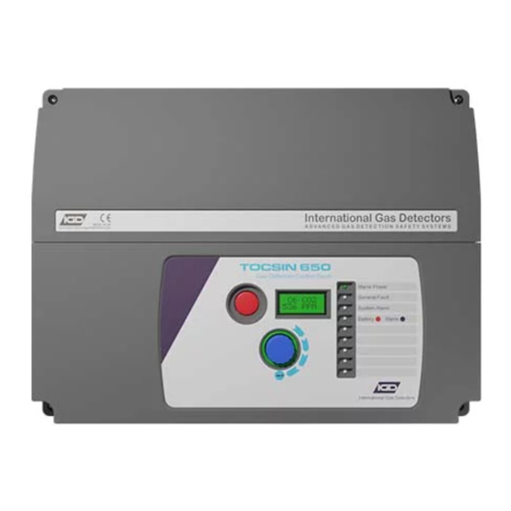
TOCSIN 650 SERIES
A d d r e s s a b l e D e t e c t o r C o n t r o l P a n e l
Triton House
Crosby Street
Stockport
Sk2 6SH
England
O p e r a t i o n a n d M a i n t e n a n c e
T el: +44 (0)161 483 1415
Fax: +44 (0) 161 484 2345
Email: sales@internationalgasdetectors.co.uk
Website: www.internationalgasdetectors.co.uk
V 3 . 1
EMS696504
FS646773
REF: T650 V3.1
Advertisement
Table of Contents

Subscribe to Our Youtube Channel
Related Manuals for IGD TOCSIN 650 SERIES


Summary of Contents for IGD TOCSIN 650 SERIES
- Page 1 2-Wire Addressable TOCSIN 650 SERIES A d d r e s s a b l e D e t e c t o r C o n t r o l P a n e l O p e r a t i o n a n d M a i n t e n a n c e V 3 .
-
Page 2: Table Of Contents
Table of Contents Specification CE Declaration Overall Dimensions Interface Wiring Highway Hub Controller Overview Relay Card Overview Relay Card Setup Addressable Detector Node Operating System Overview User Actions Menu overview Putting Into Service New Setup Sequence The Sensor ZERO Function Checking Reaction Time The Sensor CALIBRATE Function Help Section... - Page 3 The relationship between the output signal and the gas concentration is linear, the control panel interprets the signal and the gas level is displayed on the HMI or RGB backlit display. IGD hold evidence of this linear performance which is available upon request.
-
Page 4: Specification
Basic Specification 150W PSU @ 110V AC Nominal 88 to 127 V AC 50/60Hz by selection 150W PSU @ 230VAC Nominal 190 to 260V AC 50/60Hz by selection 300W PSU 88 to 260V AC 50/60Hz by selection Ambient Operating Temperature 0 to 55 Degrees Centigrade Ambient Operating Humidity 5-95% RH Non-Condensing (see sensor data) - Page 5 TUV Certificates and reports can be checked on-line at https://www.tuev-sued.de/industry_and_consumer_products/certificates London, W4 4AL Wrexham, LL13 9UZ Select Oliver IGD when prompted on the website to view certificates United Kingdom United Kingdom Issued by: Oliver IGD Limited, Stockport, SK2 6SH , United Kingdom...
- Page 6 3. Use equipment and gases traceable to a national standard. Any calibration will only be as good as the equipment and materials used. 4. IGD supply fixed flow regulators for use with IGD calibration gas bottles which supplies gas at 0.5L/Min...
- Page 7 Top Face FRONT VIEW 120.5mm 382mm 72mm Front Face Side Face Installation Cables Supported Installation Cables 2 Core 1.5mmSQ or 2.5mmSQ See IGD Cable System Calculator Typically SWA, MICC, FP200, SY, CY, System cables must be screened, refer to installers guide...
- Page 8 Copies of the installation guide are available in the downloads section of our website. Always check you are using the latest versions of the supplied manuals by checking on the IGD website. Failure to follow correct installation may result in poor performance and/or damage to system components.
- Page 9 T650 Control Panel & 2 Wire Hub Controller PCB Features Rs485 Remote Ethernet (Modbus etc) Display Battery Connection Colour HMI For Battery Backup Display TOC-650 (2x8 LCD) Fault Relay Alarm Relay 1 Alarm Relay 2 Alarm Relay 3 Power in Inputs for E-stops/Fire 24V DC Direct Beacon-Sounder O/P...
- Page 10 Tocsin 750 Addressable Relay Card Setting Relay Addresses Each Addressable relay card must have its own unique base address. This can be set on the card and is indicated below. The relays are then addresses/numbered from that base address. The example below shows a card with a default base address of 101 DOWN BUTTON...
- Page 11 Tocsin 650/750 Addressable I/O Card In all Cases: Relay contact ratings. 5A @ 250V AC Non-Inductive 5A @ 30V DC Non-Inductive Power out for 0V DC Spike suppression must be fitted use in conjunction 24V DC Note that FAULT relays are normally with relays energised on power up.
- Page 12 Relay cards also have analogue and digital inputs that can be used to read data onto the system from external devices. Setup of the inputs, type, range, addressing etc is controlled via IGD’s Android Apps. Wiring options are indicated below. Note the differences between Version 1 and 2 PCB assemblies.
- Page 13 Pellistor Port Option to Interface to MK3, MK6 or MK7 Pellistors Sounder 85dB (Option for TOC-750 Annunciators) Display 2 x 8 Programmable LCD with RGB Backlight (Option for TOC-750 Annunciators) Comm Port Supports IGD Infra-Red, PID, Toxic and Oxygen Gas Detectors...
-
Page 14: User Actions
User Actions..Day to Day Operation Once fully installed the TOC-650 controller will continuously monitor connected gas detectors and sensors and compare current values with any set alarm thresholds. The display will cycle to display each channel in turn. To access the display and switch the backlight on rotate the jog wheel Channel Gas or Reading Type... -
Page 15: Overview
Controller Interface Overview Colour Backlit LCD Display Flashes Red on alarm Flashes Yellow on Fault Detection Blue during menu operation Internal Sounder 85dB Sounds on alarm 1 or 2 activation and can be muted Alarm Indicator LED (Red) Flashes on Alarm Level 1 Continuous on Alarm Level 2 Fault Detected Indicator LED (Yellow) - Page 16 Setup option if calibrating or actions. channels, Modbus addressing etc. accessing the connected devices using a laptop running IGD Configurator software. Inhibiting the panel means it stops communicating to connected devices this prevents alarms or data clashes during PC...
-
Page 17: Toc-650 Menu Overview
TOC-650 Menu Overview 0000 PASSWORD Engineer Menu Options User Menu Options Provides access for control panel Provides access for set up and diagnostic functions maintenance functions Use this option to Use this option to FIND SEN ZERO FIND connected Input ZERO connected 1 of 12 1 of 9... - Page 18 TOC-650 Menu Overview 0000 PASSWORD Production Menu Options Provides access for control panel set up and diagnostic functions Use this option to RESET Reset the Hubcard 1 of 8 (System Re-boot) SET DFLT Reset Hubcard to 2 of 8 defaults DISP TST Display Self Test 3 of 8...
-
Page 19: Putting Into Service
Perform a Relay FIND 1 of 12 With Sensors and Relays Installed download the panel setup to IGD’s Panel Seup App to configure the system. It will be necessary to upload this once completed and re-start the controller for it to take effect. - Page 20 Warm Up Period With power applied the system should undertake its power up sequence and then commence a warm up period. The warm up period is there to allow WARMUP 600s connected detectors to stabilise before operation. Note that certain detector types, Oxygen sensors in particular may take up to 2 hours to fully stabilise.
- Page 21 Check cable and glands are of suitable type for both the area of application and load carrying capacity. Ensure terminations via glands provide a positive seal.IGD Gland packs PN TOC-GLAND achieve minimum requirements when correctly installed Leave all interfaces unplugged and check installation cabling terminations following IGD 2-Wire Installers Guide, check website for latest revisions.
- Page 22 Sequence for a Complete New Setup If you need to perform a complete new set up Then presuming the system is correctly installed and cabled the process would be as follows: 1. Use the FIND command to discover connected devices and install them to the controller 2.
- Page 23 Gas Detector ZERO Function All gas detectors will require periodic ZERO and CALIBRATION. The calibration interval depends on a number of environmental factors such as: temperature variance, exposure to wind chill, rain, humidity changes and vibration to list a few. As a guide line gas detectors should be checked at least yearly. As with any measuring instrument if calibration is not held over the intervening interval then a shorter calibration interval may be required.
-
Page 24: The Sensor Zero Function
Procedure for check reaction time to gas Ensure detector is at zero +/- 1% LEL Use standard IGD professional gas introduction kit with 2M hose. Connect calibration gas but do not turn on Using a stop watch turn on the calibration gas and time to 50% and 90% LEL... - Page 25 Once the alarm level has been set you then need to set the Alarm TYPE and decide which relay activates once the set alarm level is breached. The following sequence continues from the previous page and describes the set up sequences Scroll to change selection LEVEL TYPE...
- Page 26 Gas Detector CAL Function Gas detectors must be calibrated with known calibration gases traceable to National Standards. As previously discussed detectors require regular calibration. Calibration gases should have values chosen that either: a) Are at the alarm set point to get maximum accuracy at this point b) Are between 50 to 90% of the range of the detector.
-
Page 27: Troubleshooting
Warm up is not finished Wait till warm up is finished No response to the Electrical Fault Please contact IGD Sensor is overdue service Please contact IGD for and calibration service and calibration Inaccurate indication Damaged sensor Please contact IGD... - Page 28 401101Z Cal Adaptor (Zirconia) 401103 Cal Adaptor (MK5/6) 4011109 Gas Adaptor (TOC-30, TOC-10) 401451 Splash Guard (Tocsin 103) 401452 IGD Splash Guard 401465 Protection Filter Disk 5110101 Remote Gassing Port 5134601 40mm Stop Button 5138601 Collector Cone Ring Lock 5138701...
Need help?
Do you have a question about the TOCSIN 650 SERIES and is the answer not in the manual?
Questions and answers