Table of Contents
Advertisement
Quick Links
1 DESCRIPTION
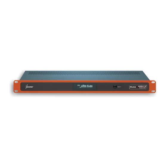
The Hono CobraNet 16.16D is a CobraNet interface designed for use in the professional installed sound market.
This device receives up to 16 channels of CobraNet and sends them to 16 AES/EBU (8 stereo) audio outputs,
while simultaneously inputting 16 channels of AES/EBU (8 stereo) audio and transmits them up to 16 channels of
CobraNet.
The Hono CobraNet 16.16D has been purposely designed to compliment and fully integrate with all of today's
CobraNet compatible DSP products. In addition, this is the ideal solution for many situations where a project
requires numerous channels of digital audio routed throughout a facility, but doesn't require a dedicated DSP
processor.
2 FEATURES
Inputs
•
Sixteen AES/EBU (8 stereo)
•
Sample Rate Converters
•
Pluggable terminal block connectors (Phoenix
style)
Outputs
•
Sixteen AES/EBU (8 stereo)
•
Sample Rate Converters
•
Pluggable terminal block connectors (Phoenix
style)
CobraNet
•
Redundant CobraNet
•
Sixteen channels of CobraNet in and out
•
Four CobraNet transmitters and eight receivers
www.audioscience.com
22 August 2011 - PRELIMINARY
H
DSP
•
Peak and RMS meters on all audio inputs and
outputs
•
Mixing of any input to any output
Power
•
Built-in 90-260VAC power supply
Chassis
•
1U rack-mount unit
•
1 RU, 19"(482mm) W x 8"(203mm) L x
1.75"(44mm) H
Control
•
All settings adjustable from ASIControl software
1
C
N
NO
OBRA
™
16X16 AES/EBU COBRANET
16.16D
ET
®
INTERFACE
22 August 2011
Advertisement
Table of Contents

Related Manuals for AudioScience Hono CobraNet Fixed Series


Summary of Contents for AudioScience Hono CobraNet Fixed Series
-
Page 1: Description
1 RU, 19”(482mm) W x 8”(203mm) L x 1.75”(44mm) H CobraNet • Redundant CobraNet Control • • Sixteen channels of CobraNet in and out All settings adjustable from ASIControl software • Four CobraNet transmitters and eight receivers www.audioscience.com 22 August 2011... -
Page 2: Architects And Engineers Specification
Sixteen channels of redundant CobraNet input and output shall be provided on an RJ-45 connector. The CobraNet interface shall be compatible with the AudioScience ASIControl software for configuration and monitoring. The CobraNet interface shall be powered by a built-in 90-240VAC power supply. -
Page 3: Block Diagram
AES/EBU In 7 AES/EBU In 8 AES/EBU In 1 AES/EBU In 2 AES/EBU In 3 AES/EBU In 4 AES/EBU In 5 AES/EBU In 6 AES/EBU In 7 AES/EBU In 8 Key: Meter AES/EBU Silence Detector Input/Output www.audioscience.com 22 August 2011... -
Page 4: Revisions
PRELIMINARY 16.16 OBRA 6 REVISIONS Date Description 22 August 2011 Preliminary. www.audioscience.com 22 August 2011... -
Page 5: Table Of Contents
Input/Output Meters – AES/EBU interface ......................19 13.3 ..................20 ESETTING THE ONFIGURATION TO EFAULT ETTINGS 13.3.1 Resetting Audio Control Settings ........................20 13.3.2 Resetting Static IP Address ..........................20 13.3.3 Resetting CobraNet Persistence.........................20 13.4 ..............................21 ETWORK NTERFACE 13.4.1 Network Mask Assignment ..........................21 www.audioscience.com 22 August 2011... - Page 6 Setting AES/EBU Clocking ..........................25 14.1.6 Input and Output Volume Adjustment ........................29 14.1.7 ClockSourceIn..............................29 14.2 ............................30 OBRA ONFIGURATION 14.2.1 Setting Up AudioScience Software to Configure CobraNet................30 14.2.2 Configuring CobraNet Using ASIControl......................32 14.2.3 References................................36 14.3 ............................36 ETWORK ONFIGURATION 14.3.1 Change IP Address ............................36 14.3.2...
-
Page 7: Table Of Figures
Figure 21. Clock source information for CobraNet devices as seen in ASIControl..........29 Figure 22. Laptop to Hono CobraNet interface connection..................31 Figure 23. ASIControl's Configure CobraNet ......................32 Figure 24. ASIControl network adapter and IP address assignments ..............37 www.audioscience.com 22 August 2011... -
Page 8: Important Safety Instructions
22 August 2011... - Page 9 3. This is a Class 1 apparatus, and as such must be connected to a mains socket outlet with a protective earthing connection. 4. The mains plug is used as the disconnect device and shall remain readily operable. www.audioscience.com 22 August 2011...
-
Page 10: Notices
INTERRUPTION) HOWEVER CAUSED AND ON ANY THEORY OF LIABILITY, WHETHER IN CONTRACT, STRICT LIABILITY, OR TORT (INCLUDING NEGLIGENCE OR OTHERWISE) ARISING IN ANY WAY OUT OF THE USE OF THIS SOFTWARE, EVEN IF ADVISED OF THE POSSIBILITY OF SUCH DAMAGE. www.audioscience.com 22 August 2011... -
Page 11: Introduction
A graphics display on the unit’s front panel shows peak meters and CobraNet status. AudioScience provides application software that may be used to set up the Hono CobraNet interfaces. ASIControl can be used to set all internal features of the unit (such as levels) and to set CobraNet routing connections to be set up between the Hono CobraNet interfaces and any other compliant CobraNet device on the network. -
Page 12: Cobranet
Similarly, the mechanism for receiving bundles is “receivers.” Each CobraNet device has several transmitters and receivers and so can simultaneously send and receive audio channels using several different bundle numbers. This capability supports audio links between many different CobraNet devices. www.audioscience.com 22 August 2011... -
Page 13: Audio Routing Channels
CobaraNet_Ch 41 rxSubMap CobaraNet_Ch 42 rxSubMap CobaraNet_Ch 43 rxSubMap CobaraNet_Ch 44 CobaraNet_Ch 45 CobaraNet_Ch 46 CobaraNet_Ch 47 CobaraNet_Ch 48 49-64 unused Connect CobraNet audio channel used in labels transmitters and receivers. Figure 3. Audio routing channel details. www.audioscience.com 22 August 2011... -
Page 14: Cobranet Transmitters
More detailed CobraNet information is available from Cirrus Logic’s website. The following links may be helpful: CobraNet Info: http://www.cobranet.info/en/support/cobranet/ CobraNet CobraCAD and CobraNet Discovery: http://www.cobranet.info/dispatch/forms/sup/boardreg/breg/BregController.jpf CobraNet Audio Routing Primer: http://cirrus.com/en/pubs/appNote/CobraNet_AudioRoutingPrimer.pdf Hardware Manual and Programmer’s Reference: http://www.cobranet.info/en/support/cobranet/developer/tech_data_sheet.html Switched Networks and Redundancy: http://www.cirrus.com/en/support/cobranet/design/switched_networks.html www.audioscience.com 22 August 2011... -
Page 15: Hardware Installation
47 to 63Hz. No selection of voltage or frequency is required, as the unit’s power supply will automatically adjust. Use only an AC power source with a protective earth ground. The Hono CobraNet interface has no power switch. Detach the AC power cord to remove power to the unit. www.audioscience.com 22 August 2011... -
Page 16: Operation
13.1.4 Loading the factory firmware image The Hono CobraNet interface can be forced to load the factory firmware image by depressing the SELECT button on front panel as power is applied to the device. Keep button depressed while power is applied. www.audioscience.com 22 August 2011... -
Page 17: Front Panel Display
X < -40 dBFS, CobraNet Rx no connect In the above table X is a peak meter reading in dBFS. Figure 4. Hono CobraNet interface display of CobraNet peak meters and bar height mapping to dBFS range www.audioscience.com 22 August 2011... -
Page 18: Cobranet Bundle Number And Channel Settings Display
• Part number (Hono CobraNet 16.16M) • Revision (R:C3) • Adapter index (I:1040) • Serial number (S:12345) • DSP firmware version (V:4.10.01) • DSP utilization in % (0%) Figure 7. Hono CobraNet interface product information display www.audioscience.com 22 August 2011... -
Page 19: Module Input/Output Meters - Analog Display
Blank(s) indicate no valid AES/EBU input signal present Hardware revision, in this case rev. B AES/EBU signal present at –40 dBFS Output sample rate, in this case 44.1kHz AES/EBU signal present at –60 dBFS Figure 9. AES/EBU module display www.audioscience.com 22 August 2011... -
Page 20: Resetting The Configuration To Default Settings
2. Depress the select button for more than 3 seconds. After you observe “RELEASE BUTTON TO: TURN PERSISTENCE OFF” release the select button. 3. Now that persistence is turned off, power cycle the Hono CobraNet interface. You should now be able to communicate with the device. www.audioscience.com 22 August 2011... -
Page 21: Network Interface
NetMask: Class A subnet: 1.0.0.0 - 127.0.0.0, Private allocation range: 10.0.0.0 - 10.255.255.255 NetMask : 255.0.0.0 Class B subnet: 128.0.0.0 - 191.255.0.0, Private allocation range: 172.16.0.0 - 172.31.255.255 NetMask : 255.255.0.0 otherwise NetMask: 0.0.0.0 www.audioscience.com 22 August 2011... -
Page 22: Configuration
PC, choose the Wave, WDM, or Combo driver to download and install (the driver type to install will be dependant upon the application used with the AudioScience adapter; consult the manufacturer of the application). If you do not have an AudioScience adapter installed in the PC, simply download the Wave driver. -
Page 23: Adapter Information
Figure 13. Level displayed by ASIControl for Line_Out 1 Level: The line out level can be adjusted by clicking the arrows or by typing values in to set the appropriate level. Consult the specification section of this datasheet for the range of supported levels. www.audioscience.com 22 August 2011... -
Page 24: Meter
14.1.4 Meter Meters in ASIControl are located on audio nodes and display the audio level as the audio signal passes through the node. Most AudioScience devices return both RMS and peak level readings and ASIControl displays both simultaneously. 14.1.4.1 Interface Figure 14. -
Page 25: Setting Aes/Ebu Clocking
Converter Transmitter From Hono interface Sample Rate AES/EBU AES/EBU Output #3 Converter Transmitter Sample Rate AES/EBU AES/EBU Output #4 Converter Transmitter Output clock to next module Figure 15. Hono CobraNet interface AES/EBU clocking for Module 1 www.audioscience.com 22 August 2011... - Page 26 Converter From Transmitter Hono interface Sample Rate AES/EBU AES/EBU Output #7 Converter Transmitter Sample Rate AES/EBU AES/EBU Output #8 Converter Transmitter Output clock to next module Figure 16. Hono CobraNet interface AES/EBU clocking for Module 2 www.audioscience.com 22 August 2011...
- Page 27 The first step in setting the AES/EBU output clocking is to select Line_Out 1in ASIControl. Figure 17. Selecting Line_Out 1 in ASIControl prior to setting Tx clock source The node pane should now display the following: Figure 18. ASIControl display of AES/EBU Line_Out 1 node controls www.audioscience.com 22 August 2011...
- Page 28 SampleClock source to be “AES/EBU In 1”. This will sync all outputs on the first module to AES/EBU In 1. To sync the outputs on the second module as well, go to Line_Out 9 and set the SampleClock source to “Previous Module”. www.audioscience.com 22 August 2011...
-
Page 29: Input And Output Volume Adjustment
Below is an image of the first volume shown in the node pane. The meter is found after the list of volumes (the Hono CobraNet interface incorporates AudioScience’s ‘anything to anywhere) mixing). Clicking on Analog_Out 1 in the topology pane of ASIControl will show a list of volumes in the node view pane. -
Page 30: Cobranet Configuration
The steps below describe how to do this. 14.2.1.1.1 Install the Network Driver When an AudioScience driver install EXE is run, three choices are made available as shown in the image below. Select “Install Standard + Network Audio Driver” when installing AudioScience CobraNet products, then run the driver install EXE as usual. - Page 31 14.2.1.1.3 Connect CobraNet Device to the Network Plug one end of an Ethernet cable into the back of the AudioScience CobraNet device. Plug the other end into the CobraNet or test network. 14.2.1.2 Setting Up AudioScience Software Using a Laptop The Hono CobraNet interface can be configured using a laptop and an Ethernet crossover cable.
-
Page 32: Configuring Cobranet Using Asicontrol
There are also four user control buttons on the bottom right. 14.2.2.1.1 Configuration Section MAC Address: Read only; displays the MAC address of the CobraNet device. IP Address: Read only, displays the assigned IP address of the CobraNet device. www.audioscience.com 22 August 2011... - Page 33 Read only; lists the type of CobraNet interface. The default setting will be the full name a CobraNet version number of the CobraNet device, for example "AudioScience Hono CobraNet 8.8M version 2.11.4(.3) CS181022." Sample Rate: Default setting is 48kHz ; a CobraNet device must run at one sample rate only. Two CobraNet devices on the same network can each operate at a different sample rate.
- Page 34 The number of times the channel transmission has been interrupted. Interruptions can be caused by loss of transmit permission from conductor (i.e. conflict with another transmitter set to the same bundle number) or by changes to txBundle. Receivers: The number of receivers requesting this bundle. www.audioscience.com 22 August 2011...
- Page 35 Updates fields and statuses. If clicked before Apply, clears any changes made. Apply: Accepts changes and leaves dialog box open. Accepts changes and closes dialog box. Cancel: Does not accept any changes made and closes dialog box. www.audioscience.com 22 August 2011...
-
Page 36: References
14.3 Network Configuration 14.3.1 Change IP Address Change the IP address of a CobraNet device here. After right clicking on a CobraNet device in ASIControl and selecting “Change IP Address…”, the dialog box below opens. www.audioscience.com 22 August 2011... -
Page 37: Configure Network Interface And Auto-Ip Assignment Range
This allows input in the last box of the Starting IP and Ending IP range. Type in the numbers required and click OK. Figure 24. ASIControl network adapter and IP address assignments <end> www.audioscience.com 22 August 2011...
Need help?
Do you have a question about the Hono CobraNet Fixed Series and is the answer not in the manual?
Questions and answers