DOLD SAFEMASTER M BG 5913.08/ 0 Series Safety Technique
Hide thumbs
Also See for SAFEMASTER M BG 5913.08/ 0 Series:
- Operating instructions manual (24 pages)
Advertisement
Quick Links
Safety Technique
Multi-Function Safety System
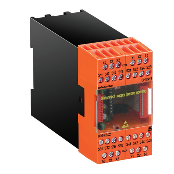
Input Module BG 5913.08/_0 _ _ _, BH 5913.08/_0 _ _ _
BG 5913
Block Diagram
start-button
output
assignment
assignment
en1
function management
(-)
X1 S44 S42 S34 S32 S24 S22 S14 S12 X2 (-)
BG 5913
output
start-button
assignment
assignment
en1
function management
(-)
X1 S
S
S
S
X2 X1 S
S
S
S
X2 X1 S
11
12
14
13
21
22
24
23
BH 5913
All data in this list are in correspondence with the technical equipment used at the time of this
version. We reserve the right to implement technical improvements and changes at any time.
SaFeMaSTer
BH 5913
M8752_a
PTC
en2
run1
run2
48 58
M8753_a
PTC
en2
run1
run2
S
S
S
X2 X1 S
S
S
S
X2 (-) 48 58
31
32
34
33
41
42
44
43
M
®
• According to EN 62 061, DIN EN ISO 13 849-1
• Category 4 to EN 954-1
• Input module for realization of
- 4 similar 2-channel inputs
- Emergency stop circuits
- Safety gate monitoring system
- Two-hand control type IIIA, IIIC acc. to DIN/EN 574
- Light curtain (LC type 4)
• The functions are selected via rotary switch
• 8 safety inputs
• 2 semiconductor outputs for status indication
• Broken wire and short circuit monitoring function with error indication
• LEDs for status indication
• Width
BG 5913.08/_0 _ _ _: 22.5 mm
BH 5913.08/_0 _ _ _: 45 mm
approvals and Marking
ET
Canada / USA
applications
Realization of fail-safe control circuits for protection of people and ma-
chinery.
Note: This module is intended for applications in which mixed safety
functions affect one common output.
Further input modules with other combinations of functions are provided
(e.g. BG 5913.08/_1_ _ _, BG 5913.08/_2_ _ _, BG 5913.08/_3_ _ _ ,
BG 5914.08/_0_ _ _, BH 5914.08/_0_ _ _ or BG 5914.08/_1_ _ _).
Circuit diagrams
A1+
48
S12
S14 S22
(-)
A1+
58
BG 5913
1
(-)
48
X1
S12 S14 S22 S24
S24 S32 S34 S42 S44
(-)
X1
X2
S32 S34 S42 S44
M8741
(-)
58
X2
BG 5913.08/_0_ _ _ / 11.05.09 e
Advertisement

Subscribe to Our Youtube Channel
Related Manuals for DOLD SAFEMASTER M BG 5913.08/ 0 Series


Summary of Contents for DOLD SAFEMASTER M BG 5913.08/ 0 Series
- Page 1 Safety Technique Multi-Function Safety System SaFeMaSTer ® Input Module BG 5913.08/_0 _ _ _, BH 5913.08/_0 _ _ _ • According to EN 62 061, DIN EN ISO 13 849-1 • Category 4 to EN 954-1 • Input module for realization of - 4 similar 2-channel inputs - Emergency stop circuits - Safety gate monitoring system...
-
Page 2: Circuit Diagrams
Circuit diagrams Setting of the Module The module is assigned to the start inputs and the safety outputs via the DIP switches. The combinations of individual functions are set via the rotary switches. To prevent accidently adjustments, these elements are covered by a front plate and are redundant. -
Page 3: Automatic Start
Function of the Two-Hand Control automatic start Automatic start is performed only when supply voltage is switched on, or when the emergency stop or stop function has been reset. S = V x T + C, where All other errors nevertheless require confirmation by a start input. a) gripping velocity V = 1 600 mm/s b) overtravel time T (s) Manual Start... - Page 4 Indication Permanently OFF Pulsing Permanent ON Activation of the all relays inactive one input function assigned safety Output due to system not available outputs is error permissible Two-hand control one input function not activated not available Activation of (LED run 2 ON) (LED run 2 ON) or the assigned or all relays inac-...
- Page 5 Function Diagramms supply voltage supply voltage (A1/A2) (A1/A2) emergency stop contact 1 emergency stop S11/S12 LED en 1 en 2 emergency stop contact 2 (enabling K1, K2) S13/S14 LED en 1 en 2 assigned start button (enabling K1, K2) output 48, LED run 1 output 48, LED run 1 (error code) (error code)
- Page 6 Function Diagramms supply voltage (A1/A2) door S1, 1 (X1/S12) door S1, 2 (X2/S14) door S2, 1 (X1/S22) door S2, 2 (X2/S24) door S3 (X1/S32) assigned start button simulation button LED en 1 en 2 (enabling K1, K2) t< t=3s output 48, LED run 1 (error code) output 58...
-
Page 7: Application Examples
application examples emergency stop 1 emergency stop 2 emergency stop 3 emergency stop 4 S12 S14 S22 S24 S32 S34 S42 S44 BG5913 error indication, waiting for start enabling active error M8947_a 4 Emergency stop circuits, 2-channel, auto/manual start with short circuit monitoring; function: 0, 2 Not-Aus 1 Not-Aus 2 Not-Aus 3... - Page 8 application examples LC 1 LC 2 LC 3 LC 4 trans- trans- trans- trans- mitter mitter mitter mitter OSSD OSSD OSSD OSSD S12 S14 S22 S24 S32 S34 S42 S44 BG5913 error indication, waiting for start enabling active error M8949_b 4 light curtains, category 4, auto/manual start;...
- Page 9 application examples safety gate 1 safety gate 2 S12 S14 S22 S24 S32 S34 S42 S44 BG5913 error indication, waiting for start enabling active error M8957_b 2 safety gates with 2 antivalent changeover contacts each; function: 5 safety gate 1 closed open simulation...
- Page 10 application examples safety gate 1 closed open simulation S12 S14 S22 S24 S32 S34 S42 S44 BG5913 error indication, waiting for start enabling active error M8961_b 1 safete gate with 3 twin contacts, manual start (plastic injection moulding machines); function: 7 two-hand 1 two-hand 2 two-hand 3...
- Page 11 application examples two-hand 1 two-hand 2 S12 S14 S22 S24 S32 S34 S42 S44 BG5913 error indication, waiting for start enabling active error M8967_b 2 two-hand controls type IIIC acc. to DIN/EN 574; function: 9 BG 5913.08/_0_ _ _ / 11.05.09 e...
- Page 12 (corresponding to test severity level 3) HF irradiation: 10 V / m IEC/EN 61 000-4-3 E. DOLD & SÖHNE KG • D-78114 Furtwangen • POBox1251•Telephone(+49)77 23 / 654-0 • Telefax (+49) 77 23 / 654-356 e-mail: dold-relays@dold.com • internet: http://www.dold.com...
Need help?
Do you have a question about the SAFEMASTER M BG 5913.08/ 0 Series and is the answer not in the manual?
Questions and answers