Advertisement
Quick Links
Light Management
Relay station universal, 8-gang
Relay station universal, 8-gang
Art. No. RS 8 REG HE
Operating instructions
1 Safety instructions
Electrical equipment may only be installed and fitted by electrically skilled persons.
Serious injuries, fire or property damage possible. Please read and follow manual fully.
Danger of electric shock. Device is not suitable for disconnection from supply voltage.
The applicable regulations and standards for SELV voltage must be observed for
installation of the control sections, the control inputs E1...E8, the activation outputs A1'...
A8' and for cable routing.
Danger of electric shock on the SELV/PELV installation. Do not connect loads for mains
voltage and SELV/PELV together.
For parallel connection of several motors to an output it is essential to observe the
corresponding instructions of the manufacturers, and to use a cut-off relay if necessary.
The motors may be destroyed.
Use only venetian blind motors with mechanical or electronic limit switches. Check the
limit switches for correct adjustment. Observe the specifications of the motor
manufacturers. Device can be damaged.
Risk of injury. Use the device only for controlling Venetian blind and roller shutter
motors or awnings. Do not use it to switch other loads.
Do not connect any three-phase motors. Device can be damaged.
These instructions are an integral part of the product, and must remain with the end
customer.
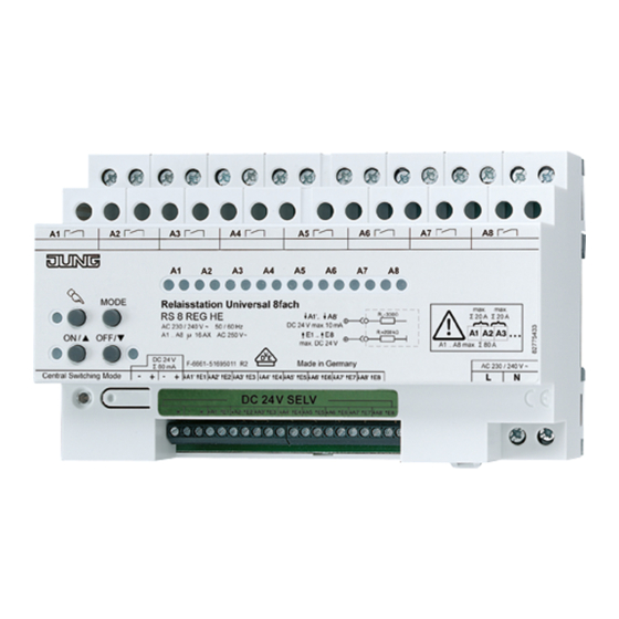
2 Device components
(1) Connection for loads A1...A8
(2) Keypad for local control
(3) Central Switching Mode, change-over button and status LED for central function
(4) Status LEDs for load outputs
(5) Connection of control sections or control voltage
82556943
J:0082556943
Figure 1: Device components
1/13
01.10.2012
Advertisement

Subscribe to Our Youtube Channel
Related Manuals for Jung RS 8 REG HE

Summary of Contents for Jung RS 8 REG HE
- Page 1 Light Management Relay station universal, 8-gang Relay station universal, 8-gang Art. No. RS 8 REG HE Operating instructions 1 Safety instructions Electrical equipment may only be installed and fitted by electrically skilled persons. Serious injuries, fire or property damage possible. Please read and follow manual fully.
-
Page 2: Operation
Light Management Relay station universal, 8-gang (6) Activation outputs A1'...A8' / Switching outputs E1...E8 (7) Connection for mains supply 3 Function Intended use Switching of lighting Switching of single-phase fan motors Switching of electrically-driven Venetian blinds, shutters, awnings and similar hangings Control by means of sensor modules, push-button modules, push-buttons 24 V, push- button modules 24 V or unlit installation buttons Installation in distribution boxes on DIN rail according to EN 60715... - Page 3 Light Management Relay station universal, 8-gang (10) LED c on: Local control or programming mode active (11) Button ON/n: Switch on load output or set mode of operation (12) LED ON/n: Status LED for load output or indication of mode of operation (13) Button OFF/o: Switch off load output or set mode of operation (14) LED OFF/o: Status LED for load output or indication of mode of operation (15) Button MODE Programming mode...
- Page 4 Light Management Relay station universal, 8-gang Switching outputs switch on. Venetian blinds move to the upper end position. Venetian blinds that are moving down will stop. Push-button outputs are activated for 0.3 seconds. Press button for Central OFF. Switching outputs switch off. Venetian blinds move to the lower end position.
- Page 5 Light Management Relay station universal, 8-gang i In Venetian blind operation, each pair of adjacent load outputs forms a blind output. In each case the left-hand load output A1, A3, ... is intended for the upwards direction, and the right-hand load output A2, A4, ... for the downwards direction. CAUTION! Overloading the device leads to excessive heating.
- Page 6 Light Management Relay station universal, 8-gang Figure 5: Wiring example with a pushbutton sensor 24 V 4-gang, push-button module 24 V 4- gang i They are only connected in the first two channels for the sake of clarity. Supplement further channels correspondingly.
- Page 7 Light Management Relay station universal, 8-gang Figure 7: Wiring example for unlit installation button Connection of one sensor module 24 V or pushbutton module 24 V to several relay stations In operation with push-button sensors 24 V or pushbutton modules 24 V, they can be connected to up to four relay stations.
- Page 8 Light Management Relay station universal, 8-gang Figure 9: Wiring example for Central ON, Central OFF i In like manner, installation buttons can also be used. Connection of one sensor module or pushbutton sensor to two relay stations Sensor modules or push-button modules can operate two relay stations together. This requires connection of both relay stations in parallel.
- Page 9 Light Management Relay station universal, 8-gang 5.2 Commissioning Setting the operating mode for load outputs A1...A8 In the state as supplied all load outputs are set to Venetian blind operation. The operating mode for the load outputs can be changed by means of the following steps. The settings are retained in the event of a mains failure.
- Page 10 Light Management Relay station universal, 8-gang To assign the central function for load output A1, press the ON/n button. The green LED of load output A1 flashes. The central function has been assigned. To remove the central function for load output A1, press the OFF/o button. The red LED of load output A1 flashes.
- Page 11 Light Management Relay station universal, 8-gang Switching on status message for sensor modules and pushbutton modules In operation with sensor modules or pushbutton modules, a status message has to be transmitted regularly. In the state as supplied this status message is switched off. Press ON/n and OFF/o buttons simultaneously for approx.
-
Page 12: Troubleshooting
Light Management Relay station universal, 8-gang Activation outputs A1'...A8' Control voltage DC 24 V SELV Current carrying capacity 10 mA Resistance Ra 330 Ω Connection rated voltage/load outputs single stranded 0.5 ... 4 mm² finely stranded with conductor sleeve 0.14 ... 2.5 mm² finely stranded without conductor sleeve 0.34 ... -
Page 13: Warranty
We provide a warranty as provided for by law. Please send the unit postage-free with a description of the defect to our central customer service office. ALBRECHT JUNG GMBH & CO. KG Volmestraße 1 58579 Schalksmühle Telefon: +49.23 55.8 06-0 Telefax: +49.23 55.8 06-2 04...
Need help?
Do you have a question about the RS 8 REG HE and is the answer not in the manual?
Questions and answers