aci Room Series Installation & Operation Instructions
Hide thumbs
Also See for Room Series:
- User manual (17 pages) ,
- Installation & operation instructions (8 pages) ,
- Installation & operation instructions (4 pages)
Advertisement
Quick Links
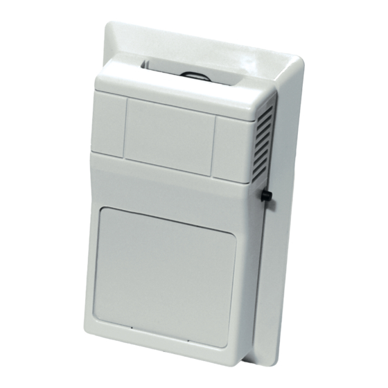
ROOM SERIES
Installation & Operation Instructions
PCB: UVC ROOM
PRECAUTIONS
•
DO NOT RUN THE WIRING IN ANY CONDUIT
WITH LINE VOLTAGE (24/120/230 VAC).
• THE OPTIONAL ACI/LCD MUST BE POWERED
WITH EITHER A 24 VAC OR 9-35 VDC POWER
SOURCE.
MOUNTING INSTRUCTIONS
Separate the cover from the base. Attach the base
directly to the wall or to a standard 2" x 4" junction
box using the (2) #6-32 x 1" screws provided.
Take care when mounting. Check local code for
mounting height requirements. Typical mounting
heights are 48-60" (1.2-1.5 m) o the ground and at
least 1.5' (0.5 m) from the adjacent wall. The sensor
should be mounted in an area where air circulation is
well mixed and not blocked by obstructions.
*Reference FIGURE 2 (next page)
For optimal temperature measurement, follow
these tips:
• Do not install on external walls.
• Avoid air registers, di users, vents, and windows.
• Avoid con ned areas such as shelves, closed
cabinets, closets, and behind curtains.
• Eliminate and seal all wall and conduit penetrations.
Air migration from wall cavities may alter
temperature readings.
• A thermally-insulated backing should be used when
tting to solid walls (concrete, steel, etc.). ACI part:
A/ROOM-FOAM-PAD
*Reference FIGURE 3 (next page)
• Do not install near heat sources, eg: lamps,
radiators, direct sunlight, copiers, chimney
walls, walls concealing hot-water pipes.
Refer to the wiring instructions (p. 2) to make
necessary connections. After wiring, attach the
cover to the base by snapping the top of the cover
on rst and then the bottom. Tighten the cover
down, using the (2) 1/16" Allen screws located in
the bottom of the housing. A 1/16" Hex driver is
needed to secure the cover to the base.
Automation Components, Inc.
2305 Pleasant View Road | Middleton, WI 53562
Phone: 1-888-967-5224 | Website: workaci.com
FIGURE 1: ROOM DIMENSIONS
ROOM, VERSION 1
[R]
2.75"
(69.85 mm)
FRONT
BOTTOM
ROOM, VERSION 2
[R2]
2.75"
(69.85 mm)
FRONT
BOTTOM
Page 1
Phone: 1-888-967-5224
Website: workaci.com
1.12"
(28.55 mm)
4.50"
(114.30 mm)
RIGHT
1.12"
(28.55 mm)
4.50"
(114.30 mm)
RIGHT
Version: 5.0
I0000130
Advertisement

Related Manuals for aci Room Series


Summary of Contents for aci Room Series
- Page 1 1.12" 2.75" (28.55 mm) (69.85 mm) • A thermally-insulated backing should be used when tting to solid walls (concrete, steel, etc.). ACI part: A/ROOM-FOAM-PAD 4.50" *Reference FIGURE 3 (next page) (114.30 mm) • Do not install near heat sources, eg: lamps,...
- Page 2 National Electric Codes. After wiring, attach the cover to the base by snapping the top of the cover on rst and then the bottom. The ACI/LCD must be powered with either a 24 VAC or 9-35 VDC power source. The ACI/LCD uses a half-wave bridge recti er to convert the AC voltage to a useable DC voltage.
- Page 3 Do not dispose of with household waste. Do not burn. WARRANTY The ACI Room Series temperature sensors are covered by ACI’s Five (5) Year Limited Warranty, which is located in the front of ACI’S SENSORS & TRANSMITTERS CATALOG or can be found on ACI’s website: www.workaci.com.
- Page 4 PRODUCT SPECIFICATIONS SENSOR NON-SPECIFIC INFORMATION Number Temperature Sensing Points: 1/16” Allen screws (2 qty) / 1/16” Hex Driver Housing Screw Size / Drive Size: “Dry Contact” Closure (Separate Input) Override Option: 1.5 to 50 °C (35 to 122 °F) | -40 to 65 °C (-40 to 149 °F) Operating | Storage Temperature Range: 10 to 95% RH, non-condensing Operating Humidity Range:...