Table of Contents
Advertisement
Quick Links
ROOM SERIES
Installation & Operation Instructions
A/TT-RSO-LCD
PRECAUTIONS
• DO NOT RUN THE WIRING IN ANY CONDUIT
WITH LINE VOLTAGE (24/120/230 VAC).
GENERAL INFORMATION
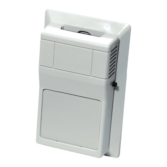
The A/TT-RSO-LCD is a temperature transmitter
product family intended for room applications.
Optional features, if selected, provide useful features
often desired in room applications, including
setpoint and override outputs. Both the temperature
transmitter and the setpoint transmitter functions
support 4-20mA, 1VDC to 5VDC, and 2VDC to 10VDC
output options. The setpoint function also supports
resistance output options, with or without an o set
resistance. The override function provides a normally
open dry-contact switch output for occupancy
indication.
MOUNTING INSTRUCTIONS
Separate the cover from the base. The ACI/LCD is
shipped as a two-piece unit. The LCD Module must be
unplugged from the 10 pin connector before the
base of the sensor may be mounted. Attach the base
directly to the wall or to a standard 2" x 4" junction
box using the (2) #6-32 x 1" screws provided.
Take care when mounting. Check local code for
mounting height requirements. Typical mounting
heights are 48-60" (1.2-1.5 m) o the ground and at
least 1.5' (0.5 m) from the adjacent wall. The sensor
should be mounted in an area where air circulation is
well mixed and not blocked by obstructions - see
FIGURE 2 (next page).
For optimal readings, follow these tips:
• Avoid con ned areas such as shelves, closed
cabinets, closets, and behind curtains.
Automation Components, Inc.
2305 Pleasant View Road | Middleton, WI 53562
Phone: 1-888-967-5224 | Website: workaci.com
FIGURE 1: ROOM DIMENSIONS
ROOM, VERSION 1
[R]
2.75"
(69.85 mm)
FRONT
BOTTOM
MOUNTING (Continued)
• Eliminate and seal all wall and conduit
penetrations. Air migration from wall cavities
may alter temperature readings.
• Do not install near heat sources, eg: lamps,
radiators, direct sunlight, copiers, chimney
walls, walls concealing hot-water pipes.
• A thermally-insulated backing should be used
when tting to solid walls (concrete, steel,
etc.).
ACI part: A/ROOM-FOAM-PAD
• Do not install on external walls.
• Avoid air registers, di users, vents, and
windows.
Refer to the wiring instructions (p. 1-2) to
make necessary connections.
LCD Installation
The LCD Module should then be gently inserted
into the
Page 1
Phone: 1-888-967-5224
Website: workaci.com
1.12"
(28.55 mm)
4.50"
(114.30 mm)
RIGHT
Version: 6.0
I0000233
Advertisement
Table of Contents

Related Manuals for aci Room Series


Summary of Contents for aci Room Series
- Page 1 BOTTOM MOUNTING INSTRUCTIONS Separate the cover from the base. The ACI/LCD is MOUNTING (Continued) shipped as a two-piece unit. The LCD Module must be unplugged from the 10 pin connector before the • Eliminate and seal all wall and conduit base of the sensor may be mounted.
-
Page 2: Wiring Instructions
Open the cover of the enclosure. ACI recommends 16 to 26 AWG twisted pair wires or shielded cable for all transmitters. Twisted pair may be used for 2-wire current output transmitters or 3-wire for voltage output. - Page 3 0.25 Watt power dissipation capabili- All ACI TT temperature transmitters can be powered from either an unregu- lated or regulated 8.5 to 32VDC power supply. The TT DO NOT support an AC input.
-
Page 4: Setpoint Control
Formula for Number of Transmitters Several transmitters may be powered from the same supply as shown in FIGURE 4 (below). Each transmitter draws 25mA; refer to the following equation to obtain the number of permissible transmitters: [# Transmitters] = [Current] / (25 mA). FIGURE 4: MULTIPLE TRANSMITTER CONNECTIONS Temp.Transmitter #1 Temp.Transmitter #1... -
Page 5: Product Specifications
50,000 Hours Minimum WARRANTY The ACI Room Series temperature sensors are covered by ACI’s Five (5) Year Limited Warranty, which is located in the front of ACI’S SENSORS & TRANSMITTERS CATALOG or can be found on ACI’s website: www.workaci.com. W.E.E.E. DIRECTIVE At the end of their useful life the packaging and product should be disposed of via a suitable recycling centre. - Page 6 NOTES Page 6 Automation Components, Inc. Version: 6.0 2305 Pleasant View Road | Middleton, WI 53562 I0000233 Phone: 1-888-967-5224 | Website: workaci.com...
- Page 7 NOTES Page 7 Automation Components, Inc. Version: 6.0 2305 Pleasant View Road | Middleton, WI 53562 I0000233 Phone: 1-888-967-5224 | Website: workaci.com...
- Page 8 Automation Components, Inc. 2305 Pleasant View Road Middleton, WI 53562 Phone: 1-888-967-5224 Website: workaci.com Page 8 Automation Components, Inc. Version: 6.0 2305 Pleasant View Road | Middleton, WI 53562 I0000233 Phone: 1-888-967-5224 | Website: workaci.com...