
Related Manuals for Sony DSRM-E1


Summary of Contents for Sony DSRM-E1
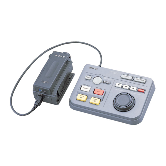
- Page 1 DSRM-E1/E1P SERVICE MANUAL US Model Canadian Model Ver 1.0 1998. 07 DSRM-E1 AEP Model DSRM-E1P Interface adaptor Controller Photo : DSRM-E1P SPECIFICATIONS DSRM-E1 : NTSC DSRM-E1P : PAL EDIT ADAPTOR MICROFILM...
- Page 2 COMPONENTS WITH SONY PARTS WHOSE PART NUMBERS NE REMPLACER CES COMPOSANTS QUE PAR DES PIÈSES APPEAR AS SHOWN IN THIS MANUAL OR IN SUPPLEMENTS SONY DONT LES NUMÉROS SONT DONNÉS DANS CE MANUEL OU DANS LES SUPPÉMENTS PUBLIÉS PAR SONY. PUB-LISHED BY SONY.
-
Page 3: Table Of Contents
TABLE OF CONTENTS Section Title Page Section Title Page GENERAL IC PIN FUNCTION DESCRIPTION Overview ................ 1-1 5-1. Edit Micro Computer HD6433837SA91F Preparations and Connections ........1-2 (CB-64/64P Board IC806) Pin Function ....... 5-1 Menus ................1-3 5-2. Front Micro Computer HD6433837SA90F Editing ................ - Page 4 DSRM-E1/E1P SECTION 1 This section is extracted from instruction manual. GENERAL...
- Page 13 1-10...
- Page 14 1-11E...
-
Page 15: Disassembly
4 Claw 5 TU cabinet (R) assembly 2 Two screws (2 × 6) 3 Claw 6 FP-246 flexible board 2-2. CIRCUIT BOARDS LOCATION CB-64 (DSRM-E1) CB-64P (DSRM-E1P) CM-58 (FRONT MICOM/EDIT MICOM) (CONTROLLER/LED DRIVE) AV-40 (DSRM-E1) AV-40P (DSRM-E1P) IN/OUT, AUDIO/VIDEO, OSD/FONT ROM,... -
Page 16: Block Diagrams
VIDEO IN Q318 Q317 AVDD B. P. F ı BUFFER BUFFER BUFFER Q105 ı +5VD DC/DC +5VD 3.58MHz : DSRM-E1 VCXO AVDD 4.43MHz : DSRM-E1P CONVERTER +5VD X301 IC307!º REC/PB +5VA 3.58MHz : DSRM-E1 +5VA 4.43MHz : DSRM-E1P IC809 IC309... -
Page 17: Control Unit Block Diagram
DSRM-E1/E1P 3-2. CONTROL UNIT BLOCK DIAGRAM CM-58 BOARD (SEE PAGE 4-33) IC102 5 REC/PB 6.2Vp-p IC102 4.195MHz JG-36 BOARD CONTROLLER MICOM (SEE PAGE 4-36) S101-S112 Q103-Q107 CN102 CN201 DATA1 FUNCTION KEY ı ı DATA1 DRIVE DATA2 DATA2 DATA0 DATA0 S201... -
Page 18: Printed Wiring Boards And 7. Schematic Diagrams
SECTION 4 PRINTED WIRING BOARDS AND SCHEMATIC DIAGRAMS 4-1. FRAME SCHEMATIC DIAGRAM 4-2. PRINTED WIRING BOARDS AND SCHEMATIC DIAGRAMS THIS NOTE IS COMMON FOR WIRING BOARDS AND SCHEMATIC DIAGRAMS (In addition to this, the necessary note is printed in each block) (For printed wiring boards) (Measuring conditions voltage and waveform) •... -
Page 19: Av-40/40P
DSRM-E1/E1P There are few cases that the part printed on this diagram isn't mounted in this model. AV-40 (DSRM-E1)/AV-40P (DSRM-E1P) (IN/OUT, AUDIO/VIDEO, OSD/FONT ROM, Y/CHROMA SEP) PRINTED WIRING BOARD • For printed wiring board. — Ref. No.: 1,000 Series —... - Page 20 DSRM-E1/E1P AV-40 (DSRM-E1)/AV-40P (DSRM-E1P) (IN/OUT) SCHEMATIC DIAGRAM AV-40/40P BOARD (1/4) 0.7 Vp-p CN102 !º 0.4 Vp-p CN102 !¡ 0.6 Vp-p CN102 8 1800 1.2 Vp-p 1800 J101 (VIDEO OUT) IN/OUT AV-40 (1/4)/AV-40P (1/4) 4-10...
- Page 21 DSRM-E1/E1P AV-40 (DSRM-E1)/AV-40P (DSRM-E1P) (AUDIO/VIDEO) SCHEMATIC DIAGRAM • See page 4-5 for AV-40/AV-40P BOARD printed wiring board. AV-40/40P BOARD (2/4) 0.7 Vp-p IC307 !º 0.6 Vp-p 500 kHz IC308 !º 3.5 Vp-p 60 Hz: DSRM-E1 50 Hz: DSRM-E1P IC308 5 3.9 Vp-p...
- Page 22 DSRM-E1/E1P AV-40 (DSRM-E1)/AV-40P (DSRM-E1P) (OSD/FONT ROM, Y/CHROMA SEP) SCHEMATIC DIAGRAMS • See page 4-5 for AV-40/AV40P BOARD printed wiring board. AV-40/40P BOARD (3/4) AV-40/40P BOARD (4/4) !º !™ 3.5 Vp-p 5.0 Vp-p 60 Hz: DSRM-E1 3.58 MHz: DSRM-E1 50 Hz: DSRM-E1P 4.43 MHz: DSRM-E1P...
-
Page 23: Cb-64/64P (Front Micon/Edit Micom)
DSRM-E1/E1P CB-64 (DSRM-E1)/CB-64P (DSRM-E1P) (FRONT MICOM/EDIT MICOM) PRINTED WIRING BOARD — Ref. No.: 1,000 Series — There are few cases that the part printed on this diagram isn't mounted in this model. • For printed wiring board. • Chip transistor... - Page 24 DSRM-E1/E1P CB-64 (DSRM-E1)/CB-64P (DSRM-E1P) (FRONT MICOM) SCHEMATIC DIAGRAM DSRM-E1P FRONT MICOM CB-64 (1/2)/CB-64P (1/2) 4-21 4-22 4-23...
-
Page 25: Printed Wiring Board
DSRM-E1/E1P CB-64 (DSRM-E1) /CB-64P (DSRM-E1P) (EDIT MICOM) SCHEMATIC DIAGRAM • See page 4-18 for CB-64/CB-64P BOARD printed wiring board. CB-64/64P BOARD (2/2) 3.5 Vp-p 8 MHz IC806 !º 6.0 Vp-p IC809 5 EDIT MICOM CB-64 (2/2)/CB-64P (2/2) 4-25 4-26... -
Page 26: Back Up Lithium) Printed Wiring Board And Schematic Diagram
LI-66 (BACK UP LITHIUM) PRINTED WIRING BOARD AND SCHEMATIC DIAGRAM – Ref. No.: 1,000 series – LI-66 BOARD(SIDE A) 1-670-617- LI-66 BOARD BH951 CN951 CB-64 (DSRM-E1) CB-64P (DSRM-E1P) CM-58 (FRONT MICOM/EDIT MICOM) (CONTROLLER/LED DRIVE) AV-40 (DSRM-E1) AV-40P (DSRM-E1P) IN/OUT, AUDIO/VIDEO, OSD/FONT ROM,... -
Page 27: Controller/Led Drive) Printed Wiring Board
PAUSE MENU CANCEL SEL/PUSH EXECUTE PREVIEW EDIT MARK IN MARK OUT 1-670-613- 1-670-613- CM-58 BOARD (SIDE A) CM-58 BOARD (SIDE B) CB-64 (DSRM-E1) CB-64P (DSRM-E1P) CM-58 (FRONT MICOM/EDIT MICOM) (CONTROLLER/LED DRIVE) D108 BZ101 D105 Q101 R115 R137 AV-40 (DSRM-E1) D109... -
Page 28: Controller/Led Drive) Schematic Diagram
DSRM-E1/E1P CM-58 (CONTROLLER/LED DRIVE) SCHEMATIC DIAGRAM CM-58 BOARD 6.2 Vp-p 4.195 MHz IC102 5 1.7 Vp-p 32.768 kHz IC102 8 IC101 S-80740AN-D4-T1 CONTROLLER/LED DRIVE CM-58 4-33 4-34... -
Page 29: Jog Shuttle) Printed Wiring Board And Schematic Diagram
– Ref. No.: 1,000 series – JG-36 BOARD(SIDE A) 1-670-614- JOG/SHUTTLE S201 JG-36 BOARD(SIDE B) 1-670-614- JG-36 BOARD (SIDE B) CB-64 (DSRM-E1) CB-64P (DSRM-E1P) CM-58 (FRONT MICOM/EDIT MICOM) (CONTROLLER/LED DRIVE) CN201 AV-40 (DSRM-E1) CN202 AV-40P (DSRM-E1P) IN/OUT, AUDIO/VIDEO, OSD/FONT ROM,... - Page 30 5-1. EDIT Micro Computer HD6433837SA91F (CB-64/64P BOARD IC806) Pin No. Pin Name Function Pin No. Pin Name Function PC0/AN8 H: Not used Not used PC1/AN9 H: Not used Not used PC2/AN10 L: Serial cont H: PAL Not used PC3/AN11 H: Not used Not used AVSS Analog ground...
- Page 31 5-2. Front Micro Computer HD6433837SA90F (CB-64/64P BOARD IC805) Pin No. Pin Name Function Pin No. Pin Name Function PC0/AN8 H: Fixed Not used PC1/AN9 H: Fixed Not used PC2/AN10 H: NTSC L: PAL Not used PC3/AN11 H: NORMAL L: Low Battery Not used AVSS Analog ground...
-
Page 32: Electrical Adjustments
DSRM-E1/E1P SECTION 6 ELECTRICAL ADJUSTMENTS During the adjustment, see the Adjustment Related Parts Arrangement on page 6-2. NTSC model : DSRM-E1 PAL model : DSRM-E1P Instruments to be Used. 1) Monitor TV 2) Frequency counter 3) NTSC/PAL pattern generator (with video output terminal) -
Page 33: Video Adjustment
6-3. Video Adjustment 3-3. APC Free-run Frequency Adjustment (OSD) • Confirm that the OSD is not displayed on the monitor TV. • Short IC303 5 pin and IC307 9 pin to the GND. 3-1. Voltage adjustment • Apply 2.4 ± 0.05 Vdc to the IC307 4 pin. •... -
Page 34: System Control Adjustment
6-4. System Control Adjustment 5) Rotating the JOG dial, confirm that the following data are dis- played on the monitor TV. 4-1. Key Input Check Slow Nomal Fast 1) Select the SERVICE mode. CW rotation 0037 0055 0090 (Refer to 6-1. How to Enter the SERVICE Mode) CCW rotation –0037 –0055... -
Page 35: Repair Parts List
3-971-948-11 BUTTON (MS) (r) 7-685-134-19 SCREW +P 2.6X8 TYPE2 NON-SLIT 3-971-969-01 BUTTON (L-PL) (PLAYER) 3-989-963-01 BUTTON, CONTROL 3-971-969-11 BUTTON (L-PL) (RECODER) X-3948-689-1 CABINET (UPPER) ASSY (DSRM-E1) 3-955-359-71 DIAL, JOG X-3948-911-1 CABINET (UPPER) ASSY (DSRM-E1P) 3-989-962-01 KNOB, SHUTTLE 3-968-001-51 BUTTON (TRANS) (MARK OUT) -
Page 36: Main Section
Description Remark Ref. No. Part No. Description Remark X-3948-837-1 CABINET (L) ASSY A-7067-174-A AV-40 BOARD, COMPLETE (DSRM-E1) 3-945-884-11 SCREW (2X6) A-7067-185-A AV-40P BOARD, COMPLETE (DSRM-E1P) A-7073-656-A LI-66 BOARD, COMPLETE * 58 1-764-310-11 PLUG, CONNECTOR X-3948-836-1 CABINET (M) ASSY (DSRM-E1) 1-654-501-11 FP-246 FLEXIBLE BOARD... -
Page 37: Electrical Parts List
µF uPD..., µPD... Ref. No. Part No. Description Remark Ref. No. Part No. Description Remark A-7067-174-A AV-40 BOARD, COMPLETE (DSRM-E1) C339 1-104-910-11 TANTAL. CHIP 15uF C341 1-164-227-11 CERAMIC CHIP 0.022uF ********************************* A-7067-185-A AV-40P BOARD, COMPLETE (DSRM-E1P) C342 1-162-970-11 CERAMIC CHIP 0.01uF... - Page 38 C709 1-164-156-11 CERAMIC CHIP 0.1uF C710 1-113-682-11 TANTAL. CHIP 33uF FL301 1-236-190-11 FILTER, LOW PASS FL501 1-233-732-21 FILTER, BAND PASS (3.58MHz) (DSRM-E1) C711 1-113-682-11 TANTAL. CHIP 33uF FL501 1-233-735-21 FILTER, BAND PASS (4.43MHz) (DSRM-E1P) C712 1-164-156-11 CERAMIC CHIP 0.1uF FL502 1-233-733-21 FILTER, LOW PASS (5.5MHz)
- Page 39 1-414-754-11 INDUCTOR 10uH R105 1-216-809-11 METAL CHIP 1/16W L303 1-412-951-11 INDUCTOR 10uH R106 1-216-809-11 METAL CHIP 1/16W L304 1-412-953-11 INDUCTOR 15uH (DSRM-E1) R107 1-216-809-11 METAL CHIP 1/16W L304 1-412-951-11 INDUCTOR 10uH (DSRM-E1P) R108 1-216-809-11 METAL CHIP 1/16W L305 1-412-951-11 INDUCTOR 10uH...
- Page 40 Part No. Description Remark R347 1-216-821-11 METAL CHIP 1/16W R520 1-218-883-11 RES,CHIP 0.50% 1/16W R353 1-216-838-11 METAL CHIP 1/16W (DSRM-E1) R355 1-216-821-11 METAL CHIP 1/16W R520 1-218-881-11 RES,CHIP 0.50% 1/16W R357 1-216-821-11 METAL CHIP 1/16W (DSRM-E1P) R360 1-216-844-11 METAL CHIP...
- Page 41 1-572-244-11 SWITCH, SLIDE (POWER) D812 8-719-820-05 DIODE 1SS181-TE85L < VIBRATOR > D813 8-719-422-97 DIODE MA8091-M-TX D814 8-719-422-64 DIODE MA8062-M-TX X301 1-579-466-11 VIBRATOR, CRYSTAL (3.58MHz) (DSRM-E1) D815 8-719-422-64 DIODE MA8062-M-TX X301 1-579-661-21 OSCILLATOR, CRYSTAL (4.43MHz) D816 8-719-422-64 DIODE MA8062-M-TX (DSRM-E1P) X302...
- Page 42 CB-64 CB-64P CM-58 Ref. No. Part No. Description Remark Ref. No. Part No. Description Remark IC808 8-759-270-03 IC SN74HC174ANS-E20 R833 1-216-817-11 METAL CHIP 1/16W IC809 8-759-350-90 IC MB89131PFM-G-274-BND IC810 8-759-497-28 IC LC35256DM-10-TLM R834 1-216-833-11 METAL CHIP 1/16W IC811 8-759-548-47 IC MX27C4000MC-12-SAX51703 R835 1-216-857-11 METAL CHIP 1/16W...
- Page 43 CM-58 Ref. No. Part No. Description Remark Ref. No. Part No. Description Remark C110 1-163-038-91 CERAMIC CHIP 0.1uF R106 1-216-049-91 RES,CHIP 1/10W C111 1-163-038-91 CERAMIC CHIP 0.1uF R107 1-216-053-00 METAL CHIP 1.5K 1/10W C112 1-104-913-11 TANTAL. CHIP 10uF R108 1-216-041-00 METAL CHIP 1/10W R109 1-216-073-00 METAL CHIP...
- Page 44 JG-36 LI-66 Ref. No. Part No. Description Remark Ref. No. Part No. Description Remark A-7073-658-A JG-36 BOARD, COMPLETE ********************* < CONNECTOR > CN201 1-770-690-11 CONNECTOR, FFC/FPC 7P CN202 1-770-690-11 CONNECTOR, FFC/FPC 7P < RESISTOR > R201 1-216-864-11 METAL CHIP 1/16W R202 1-216-864-11 METAL CHIP 1/16W...
- Page 45 DSRM-E1/E1P Sony Corporation 98G0512-1 Printed in Japan © 1998. 7 9-974-085-11 Personal A&V Products Company Published by Quarity Engineering Dept. – 80 – (Osaki East)
Need help?
Do you have a question about the DSRM-E1 and is the answer not in the manual?
Questions and answers