aci Room Series Installation & Operation Instructions
Hide thumbs
Also See for Room Series:
- User manual (17 pages) ,
- Installation & operation instructions (8 pages) ,
- Installation & operation instructions (4 pages)
Advertisement
Quick Links
ROOM SERIES
Installation & Operation Instructions
PCB: LCD
PRECAUTIONS
•
DO NOT RUN THE WIRING IN ANY CONDUIT
WITH LINE VOLTAGE (24/120/230 VAC).
• THE OPTIONAL ACI/LCD MUST BE POWERED
WITH EITHER A 24 VAC OR 9-35 VDC POWER
SOURCE.
MOUNTING INSTRUCTIONS
Separate the cover from the base. The ACI/LCD is
shipped as a two-piece unit. The LCD Module must
be unplugged from the 10 pin connector before
the base of the sensor may be mounted. Attach the
base directly to the wall or to a standard 2" x 4"
junction box using the (2) #6-32 x 1" screws
provided.
Take care when mounting. Check local code for
mounting height requirements. Typical mounting
heights are 48-60" (1.2-1.5 m) o the ground and at
least 1.5' (0.5 m) from the adjacent wall. The sensor
should be mounted in an area where air circulation
is well mixed and not blocked by obstructions - see
FIGURE 2 (next page).
For optimal readings, follow these tips:
• Avoid con ned areas such as shelves, closed
cabinets, closets, and behind curtains.
• Eliminate and seal all wall and conduit penetrations.
Air migration from wall cavities may alter
temperature readings.
• Do not install near heat sources, eg: lamps,
radiators, direct sunlight, copiers, chimney
walls, walls concealing hot-water pipes.
• A thermally-insulated backing should be used
when tting to solid walls (concrete, steel, etc.).
ACI part: A/ROOM-FOAM-PAD
• Do not install on external walls.
• Avoid air registers, di users, vents, and windows.
Refer to the wiring instructions (p. 1-2) to
make necessary connections.
Automation Components, Inc.
2305 Pleasant View Road | Middleton, WI 53562
Phone: 1-888-967-5224 | Website: workaci.com
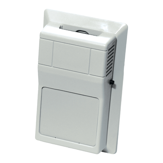
FIGURE 1: ROOM DIMENSIONS
ROOM, VERSION 1
[R]
2.75"
(69.85 mm)
FRONT
BOTTOM
MOUNTING (Continued)
LCD Installation
The LCD Module should then be gently inserted
into the 10 pin connector. Tighten the cover
down, using the (2) 1/16" Allen screws located in
the bottom of the housing. Take care to make
sure the LCD module lines up with the enclosure
LCD window. The LCD module can be bent if
adjustments are needed. A 1/16" Hex driver is
needed to secure the cover to the base.
WIRING INSTRUCTIONS
ACI recommends 16 to 26 AWG twisted pair wires
or shielded cable for all sensors. Signal wiring must
be run separate from low and high voltage wires
(24/120/230 VAC). All ACI thermistors and RTD
temperature sensors are both non-polarity and
non-position sensitive. All thermistor type room
units are supplied with a two-pole terminal
block. The number of wires needed depends on
the application.
Page 1
Phone: 1-888-967-5224
Website: workaci.com
1.12"
(28.55 mm)
4.50"
(114.30 mm)
RIGHT
Version: 4.0
I0000114
Advertisement

Related Manuals for aci Room Series


Summary of Contents for aci Room Series
- Page 1 1.12" (69.85 mm) (28.55 mm) SOURCE. MOUNTING INSTRUCTIONS 4.50" Separate the cover from the base. The ACI/LCD is (114.30 mm) shipped as a two-piece unit. The LCD Module must be unplugged from the 10 pin connector before FRONT RIGHT the base of the sensor may be mounted. Attach the base directly to the wall or to a standard 2”...
- Page 2 The ACI/LCD must be powered with either a 24 VAC or 9-35 VDC power source. The ACI/LCD uses a half-wave bridge recti er to convert the AC voltage to a useable DC voltage. Two separate cables must be pulled for the ACI/LCD to work properly.
- Page 3 ANALOG SIGNAL COMMON TO CONTROLLER Note: ACI’s stats are not two-way communicating. Communication jacks allow the user to query and modify operating parameters of the local room terminal unit from the portable operator’s terminal (laptop). This feature allows a technician to commission or service the controller via the sensor.
- Page 4 50000 Hours Minimum WARRANTY The ACI Room Series temperature sensors are covered by ACI’s Five (5) Year Limited Warranty, which is located in the front of ACI’S SENSORS & TRANSMITTERS CATALOG or can be found on ACI’s website: www.workaci.com. Page 4 Automation Components, Inc.