Table of Contents
Advertisement
2020/10/16 23:47:36 (GMT+09:00)
SERVICE MANUAL
Conditions of Use:
(1)
Please use this information only for the purpose of performing repair, maintenance and/or confi guration services of the Sony products (hereinafter the "Repair services") under the ser-
vice agreement entered into with the Sony group company (hereinafter the "Service agreement"). Using this information for any purpose other than the purpose described foregoing is
forbidden.
(2)
Only the Authorized Servicer's offi cers, employees or subcontractors (including their offi cers and employees) whose duties justify a need-to-know and who have agreed to hold
confi dential this information (collectively hereinafter the "Permitted users") are permitted to access and use this information. To disclose or disseminate to any person other than the
Permitted users is forbidden.
(3)
Destroy or erase any and all portion of this information promptly in an irrecoverable and secure fashion after achieving the purpose described in Section (1) above.
(4)
Do not copy, replicate, reproduce, alter, translate, transmit, sell, lease, or distribute this information in whole or in part without the prior written permission of the author.
(Notwithstanding foregoing, it is permitted to copy and distribute this information to the Permitted users.)
(5)
Please notify immediately any leakage, loss, theft, misappropriation, or other misuse of this information by e-mail to the following address:
somk-gcs-tissnexim-adm@jp.sony.com
(6)
In addition to the above, the terms and conditions of the Service agreement shall be applied to using this information.
Revision of Information:
This information may be changed or updated at any time without any prior notice. Please confi rm that this information is up-to-date before using it.
Sony CONFIDENTIAL
For Authorized Servicer
9-896-576-05
2020J33-1
©
2020.10
SA-WS350/WSD35
Sony Home Entertainment &
Sound Products Inc.
SYS SET
Advertisement
Table of Contents

Related Manuals for Sony SA-WS350


Summary of Contents for Sony SA-WS350
- Page 1 Conditions of Use: Please use this information only for the purpose of performing repair, maintenance and/or confi guration services of the Sony products (hereinafter the “Repair services”) under the ser- vice agreement entered into with the Sony group company (hereinafter the “Service agreement”). Using this information for any purpose other than the purpose described foregoing is forbidden.
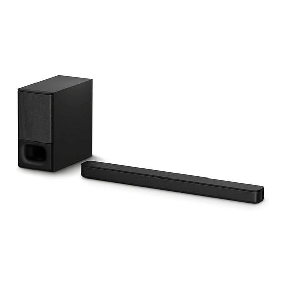
- Page 2 Subwoofer speaker system, Bass registered trademarks owned by Bluetooth (CH) reflex SIG, Inc. and any use of such marks by Sony Corporation is under license. Other Speaker trademarks and trade names are those of 160 mm (6 1/2 in) cone type their respective owners.
-
Page 3: Table Of Contents
LES DIAGRAMMES SCHÉMATIQUES ET LA LISTE DES PIÈCES SONT CRITIQUES POUR LA SÉCURITÉ DE FONC- TIONNEMENT. NE REMPLACER CES COMPOSANTS QUE PAR DES PIÈCES SONY DONT LES NUMÉROS SONT DON- NÉS DANS CE MANUEL OU DANS LES SUPPLÉMENTS PUBLIÉS PAR SONY. -
Page 4: Servicing Notes
ADVANCE PREPARATION WHEN CONFIRMING OPER- ATION All of the units included in the HT-S350 (SA-S350/SA-WS350/Re- mote control) or HT-SD35 (SA-SD35/SA-WSD35/Remote control) are required to confi rming operation of this unit. Check in advance that you have all of the units. - Page 5 : CIS area (Azerbaijan, Turkmenistan), Middle East area (Leba- non, Pakistan, Yemen), Oceania area (Seychelles) and African SA-WS350 : AEP, UK, AUS, RU, EA, BR, area (Algeria, Angola, Cameroon, Cote d’Ivoire, Egypt, Ethio- SP, E3, AR, TH, IND, LA...
- Page 6 2020/10/16 23:47:36 (GMT+09:00) SA-WS350/WSD35 Sony CONFIDENTIAL For Authorized Servicer RESET METHOD (for bar speaker) WIRELESS CONNECTION (LINK) WORK OF THE BAR After the repair of this unit is completed, be sure to reset the bar SPEAKER AND THE SUBWOOFER speaker by referring to the following before checking the operation.
- Page 7 2020/10/16 23:47:36 (GMT+09:00) SA-WS350/WSD35 Sony CONFIDENTIAL Ver. 1.4 For Authorized Servicer • When the subwoofer is repaired What to do if only the bar speaker or the subwoofer are Procedure: brought in for repair 1. Touch the [ ] button on the bar speaker to turn the power on.
-
Page 8: Disassembly
2020/10/16 23:47:36 (GMT+09:00) SA-WS350/WSD35 Sony CONFIDENTIAL SECTION 2 For Authorized Servicer DISASSEMBLY • This set can be disassembled in the order shown below. 2-1. DISASSEMBLY FLOW 2-2. AMP BLOCK 2-10. LED BOARD, FRONT PANEL ASSY (CA1_SW) (Page 9) (Page 17) 2-11. SPEAKER UNIT (CA1_SW) 2-3. -
Page 9: Amp Block
2020/10/16 23:47:36 (GMT+09:00) SA-WS350/WSD35 Sony CONFIDENTIAL For Authorized Servicer Note: Follow the disassembly procedure in the numerical order given. 2-2. AMP BLOCK Note 1: When removing the AMP block, do not remove the eight screws at the v mark screws of figure below. -
Page 10: Ac Cord
2020/10/16 23:47:36 (GMT+09:00) SA-WS350/WSD35 Sony CONFIDENTIAL Ver. 1.2 For Authorized Servicer 2-3. AC CORD top side AMP block rear side cord bush 5 AC cord (2104) 3 Draw out the AC cord with AC cord cord bush (2104) from the [black] [brown] hole in the AMP block. -
Page 11: Main Board
2020/10/16 23:47:36 (GMT+09:00) SA-WS350/WSD35 Sony CONFIDENTIAL For Authorized Servicer 2-4. MAIN BOARD Note 1: If MAIN board is replaced with a new part, refer to “RESET METHOD” on page 6, be sure to perform the reset. Also, after completing the reset, refer to “WIRELESS CONNECTION (LINK) WORK OF THE BAR SPEAKER AND THE SUBWOOFER”... -
Page 12: Power Board
2020/10/16 23:47:36 (GMT+09:00) SA-WS350/WSD35 Sony CONFIDENTIAL Ver. 1.2 For Authorized Servicer 2-5. POWER BOARD top side AMP block 2 SPK cord power cable SPK cord power SPK cord power connector cable connector cable connector (POWER board: CN2) is fully inserted. is not fully inserted. -
Page 13: Key Board, Button
2020/10/16 23:47:36 (GMT+09:00) SA-WS350/WSD35 Sony CONFIDENTIAL For Authorized Servicer 2-6. KEY BOARD, BUTTON top side AMP block The rear side is terminal side. connector (CN1) on the KEY board 1 Unlock the connector. 2 FFC cable (12 core) connected to the MAIN board... -
Page 14: Mini Jack Board
2020/10/16 23:47:36 (GMT+09:00) SA-WS350/WSD35 Sony CONFIDENTIAL For Authorized Servicer 2-7. MINI JACK BOARD top side AMP block connector (CN1) on 1 Unlock the the MINI JACK board connector. 2 FFC cable (6 core) connected to the rear side MAIN board The rear side is terminal side. -
Page 15: Bt Module (Sw)
2020/10/16 23:47:36 (GMT+09:00) SA-WS350/WSD35 Sony CONFIDENTIAL For Authorized Servicer 2-8. BT MODULE (SW) Note: If BT module (SW) is replaced with a new part, refer to “RESET METHOD” on page 6, be sure to perform the reset. Also, after completing the reset, refer to “WIRELESS CONNECTION (LINK) WORK OF THE BAR SPEAKER AND THE SUBWOOFER”... -
Page 16: Ffc Cable (6 Core), Ffc Cable (12 Core)
2020/10/16 23:47:36 (GMT+09:00) SA-WS350/WSD35 Sony CONFIDENTIAL For Authorized Servicer 2-9. FFC CABLE (6 CORE), FFC CABLE (12 CORE) 8 FFC cable (12 core) top side (for MAIN board – KEY board connection) rear plate block (See Fig. B) boss 4 two screws... -
Page 17: Led Board, Front Panel Assy (Ca1_Sw)
2020/10/16 23:47:36 (GMT+09:00) SA-WS350/WSD35 Sony CONFIDENTIAL For Authorized Servicer 2-10. LED BOARD, FRONT PANEL ASSY (CA1_SW) 1 Insert a flat-head screwdriver into the two slits on the bottom of the unit, and 3 While moving the jig in the direction open a gap between the front panel assy of the arrow, remove five bosses. -
Page 18: Speaker Unit (Ca1_Sw)
2020/10/16 23:47:36 (GMT+09:00) SA-WS350/WSD35 Sony CONFIDENTIAL For Authorized Servicer 2-11. SPEAKER UNIT (CA1_SW) Note 1: When installing the speaker unit (CA1_SW), make the position of terminals as shown in the figure below. – – 1 six screws top side (BVTP4 4 speaker unit... -
Page 19: Diagrams
2020/10/16 23:47:36 (GMT+09:00) SA-WS350/WSD35 Sony CONFIDENTIAL SECTION 3 For Authorized Servicer DIAGRAMS 3-1. BLOCK DIAGRAM Mono Audio In 3 pins (Program Update) (Audio In & WIRE_ON) UART BT Module Audio Soundbar Proc (BTL) (2 colors) 2 Keys Vdc (+25.8V) SMPS Input Regulators Subwoofer SYS SET... - Page 20 2020/10/16 23:47:36 (GMT+09:00) SA-WS350/WSD35 Sony CONFIDENTIAL Ver. 1.4 For Authorized Servicer THIS NOTE IS COMMON FOR PRINTED WIRING BOARDS AND SCHEMATIC DIAGRAMS. (In addition to this, the necessary note is printed in each block.) For Printed Wiring Boards. For Schematic Diagrams. Note: Note: •...
-
Page 21: Printed Wiring Board - Main Board
2020/10/16 23:47:36 (GMT+09:00) SA-WS350/WSD35 Sony CONFIDENTIAL For Authorized Servicer 3-2. PRINTED WIRING BOARD - MAIN Board - • See page 20 for Circuit Boards Location. • : Uses unleaded solder. MAIN BOARD (SIDE A) C188 R194 R205 C191 R202 R219 R239 R231... -
Page 22: Schematic Diagram - Main Board (1/4)
2020/10/16 23:47:36 (GMT+09:00) SA-WS350/WSD35 Sony CONFIDENTIAL For Authorized Servicer 3-3. SCHEMATIC DIAGRAM - MAIN Board (1/4) - MAIN BOARD (1/4) TP12 24V ==> 5V (2000mA) VOUT=0.596*(1+R1/R2) TPAD60-OG-GP +5V_STB Standby +24V SCD1U10V2KX-5GP BOOT1 100KR2F-L1-GP BOOT U1_EN IND-150UH-11-GP TP156 TPAD60-OG-GP TPS54202DDCR-GP 13K3R2F-L1-GP 511KR2F-GP U1_EN 105KR2F-1-GP 24V ==>... -
Page 23: Schematic Diagram - Main Board (2/4)
2020/10/16 23:47:36 (GMT+09:00) SA-WS350/WSD35 Sony CONFIDENTIAL For Authorized Servicer 3-4. SCHEMATIC DIAGRAM - MAIN Board (2/4) - MAIN BOARD (2/4) 5V ==> 3.3V Standby AMP PVDD Power Ctrl (1A max) TPAD60-OG-GP TPAD60-OG-GP +24V +24_PVDD TLV1117LV33DCYR-GP-U +24V_D4 AMP_24V_MOS_RL R232 470KR2F-GP +5V_STB TP11 AON7403-GP-U... -
Page 24: Schematic Diagram - Main Board (3/4)
2020/10/16 23:47:36 (GMT+09:00) SA-WS350/WSD35 Sony CONFIDENTIAL For Authorized Servicer 3-5. SCHEMATIC DIAGRAM - MAIN Board (3/4) - MAIN BOARD (3/4) I2S_LRCLK_1 TAS_SD_1 TPAD40-GP TPAD40-GP TAS_XPDN_1 TP169 TP161 PCONT TPAD40-GP TPAD40-GP TP170 TP162 PVDD_STBY_1 BT_LED1 TPAD40-GP TPAD40-GP TP171 TP183 WIRED_ON_1 BT_LED0 TPAD40-GP TPAD40-GP... -
Page 25: Schematic Diagram - Main Board (4/4)
2020/10/16 23:47:36 (GMT+09:00) SA-WS350/WSD35 Sony CONFIDENTIAL For Authorized Servicer 3-6. SCHEMATIC DIAGRAM - MAIN Board (4/4) - MAIN BOARD (4/4) +3V3_STB +3V3_STB Key and update to BT KEY_PAIR KEY_PAIR UART_TX KEY_PAIR_1 BAOT-CON4-S3-GP UART_TX KEY_PAIR_1 UART_RX PCONT 4,5,6 UART_RX PCONT BT_BOOT BT_BOOT R223... -
Page 26: Printed Wiring Board - Mini Jack Board
2020/10/16 23:47:36 (GMT+09:00) SA-WS350/WSD35 Sony CONFIDENTIAL For Authorized Servicer 3-7. PRINTED WIRING BOARD - MINI JACK Board - 3-8. SCHEMATIC DIAGRAM - MINI JACK Board - • See page 20 for Circuit Boards Location. • : Uses unleaded solder. MINI JACK BOARD... -
Page 27: Printed Wiring Board - Led Board
2020/10/16 23:47:36 (GMT+09:00) SA-WS350/WSD35 Sony CONFIDENTIAL For Authorized Servicer 3-9. PRINTED WIRING BOARD - LED Board - 3-10. SCHEMATIC DIAGRAM - LED Board - • See page 20 for Circuit Boards Location. • : Uses unleaded solder. LED BOARD LED BOARD (SIDE A) -
Page 28: Printed Wiring Board - Key Board
2020/10/16 23:47:36 (GMT+09:00) SA-WS350/WSD35 Sony CONFIDENTIAL For Authorized Servicer 3-11. PRINTED WIRING BOARD - KEY Board - 3-12. SCHEMATIC DIAGRAM - KEY Board - • See page 20 for Circuit Boards Location. • : Uses unleaded solder. KEY BOARD KEY BOARD (SIDE A) -
Page 29: Printed Wiring Board - Power Board
2020/10/16 23:47:36 (GMT+09:00) SA-WS350/WSD35 Sony CONFIDENTIAL For Authorized Servicer 3-13. PRINTED WIRING BOARD - POWER Board - • See page 20 for Circuit Boards Location. • : Uses unleaded solder. POWER BOARD (COMPONENT SIDE) POWER BOARD (CONDUCTOR SIDE) SA-WS350/WSD35 SYS SET... -
Page 30: Schematic Diagram - Power Board
2020/10/16 23:47:36 (GMT+09:00) SA-WS350/WSD35 Sony CONFIDENTIAL For Authorized Servicer 3-14. SCHEMATIC DIAGRAM - POWER Board - POWER BOARD SA-WS350/WSD35 SYS SET... -
Page 31: Exploded Views
2020/10/16 23:47:36 (GMT+09:00) SA-WS350/WSD35 Sony CONFIDENTIAL Ver. 1.2 SECTION 4 For Authorized Servicer EXPLODED VIEWS Note: • -XX and -X mean standardized parts, so • The mechanical parts with no reference The components identifi ed by mark 0 they may have some diff erence from the... -
Page 32: Amp Section
2020/10/16 23:47:36 (GMT+09:00) SA-WS350/WSD35 Sony CONFIDENTIAL Ver. 1.2 For Authorized Servicer 4-2. AMP SECTION not supplied not supplied not supplied not supplied (See Note 1) not supplied not supplied FFC1 (See Note 2) not supplied not supplied (model number label) FFC3 (See Note 2) -
Page 33: Electrical Parts List
2020/10/16 23:47:36 (GMT+09:00) SA-WS350/WSD35 Sony CONFIDENTIAL Ver. 1.4 SECTION 5 For Authorized Servicer MAIN MINI JACK ELECTRICAL PARTS LIST POWER Note: • Due to standardization, replacements in • SEMICONDUCTORS Among mounted electrical parts on each the parts list may be diff erent from the parts In each case, u: μ, for example:... - Page 34 Addition of Part No. for FOOT (Ref. No. 5) (SMR-18042) 2019.06 Addition of CH, RU, BR, SP, TW, AR, TH and LA models (SA-WS350) 2020.06 Addition of “NOTE OF REPLACING THE FUSE” on SERVICING NOTES Change of model number label (SA-WS350: AEP, UK/SA-WSD35: AEP, UK) (SMR-20002/20006) 2020.10...
Need help?
Do you have a question about the SA-WS350 and is the answer not in the manual?
Questions and answers